This calculator can be used to convert the measurement taken with an oscilloscope to complex impedance and power information. See instructions below.
Instructions
This calculator is designed to take the measurements of a complex load from a two channel oscilloscope and translate them into R, X, Return Loss, VSWR, dissipated power, etc.
In order to do the measurement, one of these configurations below is needed. When executing the calculation, select “configuration A” or “configuration B” according to your probes configuration.
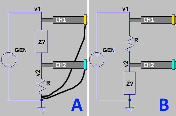
“Z?” is the unknown load. “R” is a known resistor used by channel 2 to measure the current and phase. Its value must be as little as possible to limit the impact on the overall impedance of the circuit, but it must be big enough to produce a voltage drop that can be read by the oscilloscope with good precision.
The probes should be set to 10x to reduce their impact on the impedance of the circuit.
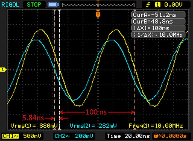
This is an example of a oscilloscope reading:
Input parameters
- Vrms on CH1 – the RMS votage reading on channel 1; in the example above the CH1 trace is yellow and the Vrms value is 880mV;
- Vrms on CH2 – same as above but for channel 2 (cyan);
- Wavelength – the length of a full wave on the scope; in the example above the Δt is taken (100nS), but any other measurement method (including a ruler on the screen) is ok;
- Phase difference – the distance between the two tracks in the same measurement units of “Wavelength”; in the example above, 5.84ns:
This value is to be specified as negative if measurement from CH1 to CH2 goes leftwards (as in the example above).
positive if measurement from CH1 to CH2 is taken going rightwards - RΩ – the value of the test resistor “R” (for example 12Ω);
- Frequency in MHz – frequency at which the measurement has been taken
Formulae
Below the formulae that are used in this calculator.
Input values:
| V1 | Vrms on CH 1 |
| V2 | Vrms on CH 2 |
| WL | Wavelengt |
| PD | Phase difference |
| RI | R Ω |
| FR | Frequency in MHz |
Calculations
Reference impedance, used for VSWR calculation:
Z0 = 50 + 0j
Define voltages in complex form
OV1 = V1 + 0j
OV2 = V2∠ -2Π(PD/WL)
Define R as a complex number
R = RI + 0j
Configuration ‘A’
Calculate current on R:
OI =OV2 / R
Calculate Z:
OZ= (OV1 – OV2) / OI
Power dissipated by Z:
OPZ = (|OV1 – OV2|2) / OZ
Power dissipated by R
OPR = |OV2|2/R
Configuration ‘B’
Calculate current on R:
OI = (OV1-OV2) / R
Calculate Z:
OZ= OV2 / OI
Power dissipated by Z:
OPZ = |OV2|2 / OZ
Power dissipated by R:
OPR = |OV1 – OV2|2 / R
Common calculations
Calculate the refelction coefficient:
RC = (OZ – Z0) / (OZ + Z0)
Calculate the return loss:
RL = -20 log10(|RC|) ∠ ARG(RC)
Calculate VSWR:
VSWR = (1 + |RC|) / (1 – |RC|)
Parallel components calculations
Calculate Q:
Q = IM(OZ)/RE(OZ)
ParallelR = (Q*Q+1)*RE(OZ)
ParallelX = ParallelR / Q
