The NEC-2 engine, used by many antenna simulation free programs, has no direct way to simulate insulated wires.
This is a pity, because it is interesting to see what happens with antennae made of cables with a lower velocity factor.
So, here it is a solution.
The principles
The solution is based on the fact that having a cable with lower velocity factor is somewhat equivalent of having a distributed inductance over the wire.
NEC-2, through the LD card, allows us to define such distributed inductance. The problem is now to establish exactly which is the inductance value in Henry per meter.
Unfortunately, the choice H/m value depends also on the wire diameter/frequency ratio, so we must have at idea of the frequency we’ll be using before calculating the inductance.
Mesasure the wire velocity factor
Before we can go on, there is an information we need: the velocity factor of the wire we are working on.
I usually do it straight away using my miniVNA, which “measure velocty factor” feature proved to be quite accurate. Otherwise, you might use tables or formulas or whatever else gives you this value.
Calculating the inductance
First, we define a dipole in empty space and tune it to work on the frequency you have chosen.
We start with this specification, which is a “test bed” that can be used by the 4NEC2 optimizer:
SY vf=1 ' Velocity factor
SY wireDiam=0.002 ' Diameter of the wire
SY MHz=29.98 ' FrequencySY picoH=1000 ' Distributed inductance, pH/mSY len1=299.8/MHz/2 ' 1/2 wave in empty spaceSY len=len1*vf
GW 1 21 -len/2 0 0 len/2 0 0 wireDiam
GE 0
LD 2 1 1 21 0 picoH*1e-9 0
GN -1
EK
EX 0 1 50% 0 1 0 0
FR 0 0 0 0 MHz 0
EN
For example, we want to calculate the distributed inductance for a velocity factor of 0.73 at 14MHz on a wire that has a diameter of 3mm:
SY vf=0.73 ' Velocity factor
SY wireDiam=0.003 ' Diameter of the wire
SY MHz=14 ' FrequencySY picoH=1000 ' Distributed inductance, pH/mSY len1=299.8/MHz/2 ' 1/2 wave in empty spaceSY len=len1*vf
GW 1 21 -len/2 0 0 len/2 0 0 wireDiam
GE 0
LD 2 1 1 21 0 picoH*1e-9 0
GN -1
EK
EX 0 1 50% 0 1 0 0
FR 0 0 0 0 MHz 0
EN
Now, run the optimization of “picoH” requiring the minimum reactance (X).
This is an example with 4NEC2 optimizer:
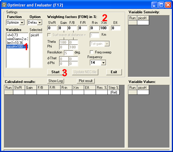
After a couple of runs, the optimizer will find the right impedence value: in this case is 985.
Now, I can design my 20m antenna using the insulated wire!
I can also see the velocity factor that 4NEC2 considers for “raw” copper wires of the given diameter at a given frequency.
I have to force picoH=0, set the frequency and diameter (same as above)
SY vf=1 ' Velocity factor
SY wireDiam=0.003 ' Diameter of the wire
SY MHz=14 ' FrequencySY picoH=0 ' Distributed inductance, pH/mSY len1=299.8/MHz/2 ' 1/2 wave in empty spaceSY len=len1*vf
GW 1 21 -len/2 0 0 len/2 0 0 wireDiam
GE 0
LD 2 1 1 21 0 picoH*1e-9 0
GN -1
EK
EX 0 1 50% 0 1 0 0
FR 0 0 0 0 MHz 0
EN
Then I can optimize using “vf” as a variable instead of “picoH” searching for zero reactance.
As we can see, the resulting velocity factor is, in this example, 0.9654.
73 de IZ2UUF

Leave a Reply