
A common topic among ham radio operators is about power lost due to high VSWR when feeding an untuned antenna. A very frequent explanation about why this should (or should not) be a concern, is more or less like this:
The power generated by the transmitter enters the coaxial cable and runs towards the antenna. When it reaches the load (the antenna) it encounter a mismatch; due to this mismatch, some power is transferred to the antenna, while the rest is reflected back and therefore lost. A tuner can be added between the transceiver and the line, but it will just “fool” the transceiver to believe the load is 50Ω: nevertheless the mismatch is still there with all of its consequent losses.
The amount of reflected (thus supposedly lost) power is directly related to VSWR and usually quantified in tables like this:
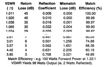
The Mismatch Loss in dB is calculated with the formula below:

For example, with VSWR=5.85, according to this approach, more than 50% of the power should be lost (-3.021 dB).
Where does the energy go?
Many sources do not even bother to consider where the “lost power” is supposed to go: simply, it disappears. However we all learned in our high school Physics class that energy can not disappear into nothing.
Some more advanced sources, instead, explain that the reflected power runs back into the transmission line until it bangs against the transmitter, whose internal resistance dissipates it. And if it bangs too hard, it can destroy the transmitter, like a train crashing into a wall.
According to this theory, the complete process should be:
- energy leaves the transmitter and enters the coaxial cable;
- while running in the transmission line, some energy is dissipated as heat (all hams are aware of the dBs lost for every 100m/100ft at a given frequency of their favorite coaxial cables);
- the surviving energy hits the mismatch point, where the high-VSWR antenna is connected to the coax;
- given a VSWR value, a fixed percentage of energy goes to the antenna, while the remaining is “sent back” on the same coax;
- the returning energy runs back on the cable and gets dissipated again by the same cable attenuation that it met on its forward run;
- finally, the remaining reflected energy hits the transmitter and it is completely dissipated by the generator internal resistance;
Let us make an example. We have a cable that has 1dB of attenuation at the frequency in use and we have an antenna presenting VSWR=5.85, thus a Mismatch Loss of 3.021dB: we should expect to have 3.021dB+1dB=4.021dB attenuation, i.e. only 40W out of 100 that go on the air.
But… is that true?
Experiments setup
In order to verify the theory above, I connected my function generator to channel #1 of my oscilloscope; after that, I connected 24.9m of RG-58, then channel #2 of the scope and finally the load resistor representing the antenna. This setup will allow us to see the voltage entering the line and the voltage entering the load after having traversed the entire cable.
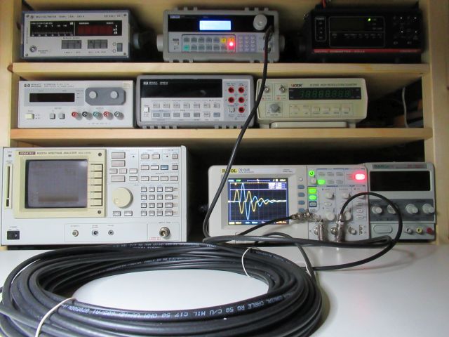
Knowing the voltage V and the complex impedance Z, we can calculate the resulting power with P=V2/Z. Thus, with this setup and the help of a VNA, we can measure the power entering the coax and the power received by the load without impedance restrictions. The difference will reveal us the real power loss.
Before starting the experiments, I carefully measured this test cable with my network analyzer. It resulted having a velocity factor of 0.6636 and, at 5MHz, an attenuation of 0.823dB.
Experiment 1: matched load
In this experiment, the line is terminated with a 50Ω load, thus it is perfectly matched. In the picture below we can see the function generator sending a single 5MHz sine wave:
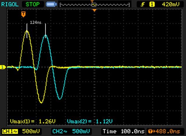
As expected, we have the generated pulse (yellow) developing on the 50Ω characteristic impedance of the coaxial cable. After 124ns, the same pulse reaches the 50Ω load. Considering that light travels 300mm every 1ns, we have 124 * 300 * 0.6636 = 24686mm = 24.7m, which is fairly close (±1ns) to the measured length of 24.9m.
Being R the same on both sides (i.e. 50Ω), we can calculate the power ratio squaring the ratio of peak voltages: (1.12/1.26)2=0.79, which is a loss of 1.02dB, which is the same as the VNA measure ±0.2dB.
Now we can set the generator to send a continuous stream of sinewaves at 5MHz:

As expected, we obtain the same pattern as before but repeated over and over: voltages and timings are absolutely identical.
So far so good.
Experiment 2: mismatched load
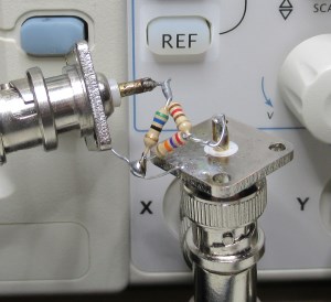
In order to test the behavior of the transmission line when loaded with high VSWR, I prepared a female SMA connector with a 270Ω SMD resistor soldered on it:
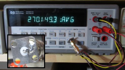
This load produces VSWR=5.403 and, according to the Mismatch Loss table above, a loss of 2.779dB (53% to the antenna, 47% lost).
Let us now send again a single 5MHz pulse and see what happens:
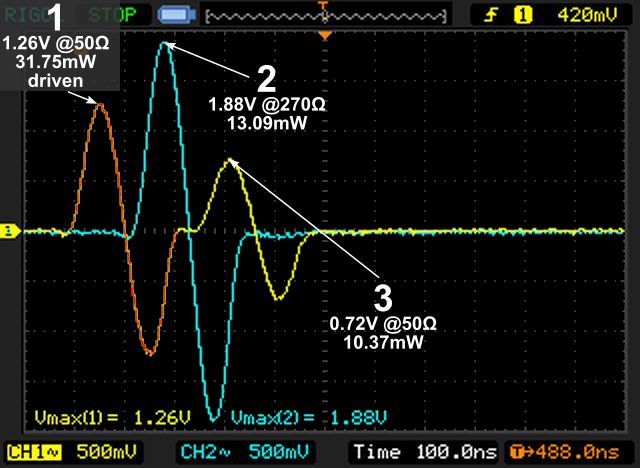
What we see now is something a bit different than before. The initial pulse (1) is identical as the one of experiment #1 (1.26V peak). When it arrives to the 270Ω load (2) 124ns later, the voltage is much higher (1.88V peak). Then, after 124ns, a new peak (3) appears on channel 1, the load side.
Let’s see what happened. The initial pulse (1) is driven on the transmission line, that at that time appears as a 50Ω load. There should be no surprise to observe that the first pulse is always identical among all the experiments: since information can not travel at infinite speed, the generator can not know instantly that at the end of the line that there is a different load than before. Therefore, the first peak must be identical to the ones we have seen before when we had the 50Ω load – and so it is.
The peak power sent by the generator in the coaxial cable is 1.26V on 50Ω (1), which makes 31.75mW. The peak then travels along the line generating heat; when reaches the other end, after 124ns, it should have lost 0.823dB: the power available at (2) should be 26.27mW.
At this point the wave encounters the mismatch. The tables say that, due to VSWR=5.403, only 52.7% of this power should be delivered to the load, that is 13.85mW. If we look at the 1.88V peak on 270Ω we have 13.09mW which confirms it.
We have now a remainder of 12.42mW that have not been delivered to the 270Ω load. This power is bounced back and travels the coaxial cable in the other direction, loosing again 0.823dB. The power that reaches back the generator should be 10.28mW: the value at point (3) is 0.72V @50Ω, which makes 10.37mW, again perfectly in line with expectations.
At this point the returning peak (3) encounters the function generator output port which offers 50Ω, i.e. a perfect match: the returning wave heats up the 50Ω resistor inside the function generator and disappears.
So far, the initial theory is perfectly confirmed: the mismatched load has consumed the exact percentage of power and the rest has been bounced back and dissipated in the generator.
The power delivered to the load was expected to be attenuated of 0.823dB (cable loss) + 2.779dB (mismatch loss)=3.602dB. Using a script and the binary data downloaded from the oscilloscope, I integrated the energy contained in the driven curve (orange, 3.040429nJ) and the load curve (blue 1.313286nJ): their ratio, 0.4319, accounts to 3.646dB of attenuation, which is almost a perfect match with the expected 3.602dB!
Experiment 3: mismatched load and generator
This time we shall repeat the experiment 2, but instead of having a 50Ω generator, we shall use a different impedance. In order to attain it, I prepared a matching attenuator with 10.28dB of attenuation and a reverse impedance of 144.5Ω. This is like to have a generator which output impedance is not 50Ω anymore, but 144.5Ω.
I increased the function generator voltage to compensate the attenuator so the same 1.26V initial peak was generated again in the transmission line. This is what happened:
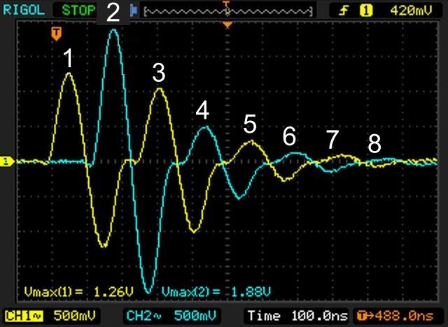
Here we can see a different story. The initial stimulus (1) is the same as before as predicted; it travels until it reaches the 270Ω load (2) which reacts exactly as in experiment #2, reflecting the 47.3% of the received power. However this time the power coming back finds another mismatch, the 144Ω attenuator pad (3), and it is reflected back again towards the 270Ω load (4). Then it bounces back and forth over and over until all the power is gone. As it appears clearly, this time more energy is delivered to the load, although in multiple steps.
Using the energy integration method, I calculated the energy actually delivered to the 270Ω load. This time the loss is only 3.271dB: i.e. the load received 0.37dB more than before.
The first cracks in the initial theory begin to appear. The initial claim is founded on a fixed relation VSWR->loss, but a very simple experiment like this shows a case where it does not work. Same identical initial wave, same line, same load, same VSWR, two different results just by changing the impedance of the generator?
Experiment 4: let’s the magic begin
So far we have seen with that same setup, two different generator impedances feeding exactly the same power can change the amount of power delivered to the load. The experiment above shows that the power not delivered to the load is dissipated as heat by the cable itself and by the internal resistance of the generator.
We shall now execute another experiment: this time, we will repeat experiments #2 (50Ω generator, 270Ω load) and #3 (144Ω generator, 270Ω load) but feeding a continuous sine wave. In both tests, the generator is set with the identical voltage level that in the previous tests generated the 1.26V initial peak.
Here they are:
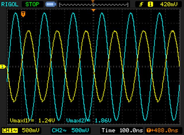
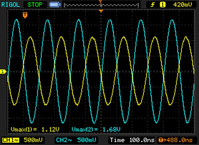
When feeding the circuit with a continuous sine wave, something weird seems to happen. First we note that by looking at these screenshot, there is no clue of any bouncing anymore: both tests generate a nice yellow sine wave that propagates 124ns ahead to a nice blue sine wave on the load.
Even more interesting is that the peak CH1/CH2 voltages, although not identical among the two tests, hold exactly the same ratio:
- 1.86/1.24 = 1.5
- 1.68/1.12 = 1.5
Unlike the single-shot tests #2 and #3, the continuously fed lines are delivering exactly the same amount of power, no matter what the generator impedance is.
In other words, when the generator sends a single shot, part of the energy is bounced back and dissipated by its internal impedance. As we saw, different generator impedance, different amount of energy dissipated, different amount of energy successfully delivered to the load. But if the generator sends a continuous flow of sine waves, we experience a completely dissimilar behavior: no matter of which is the generator impedance, the very same percentage of the power that enters the coaxial cable is delivered to the load.
So, what’s going on?
Behavior of a transmission line
Without entering into the details, we can have an hint of the reason why a transmission line fed continuously behaves differently from one that receives a single pulse from the picture below:
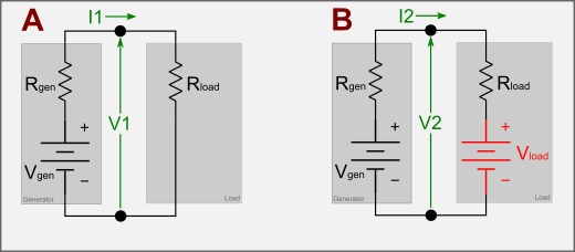
In picture “A” we have a voltage generator Vgen with its internal resistance Rgen feeding a load made of the resistance Rload. What the generator will see is a voltage V1 and a current I1 developing on its terminals: therefore, it will see an impedance Z1=V1/I1 which, in this case, is the same as Rload.
The reflected power forms a voltage wave that travels back on the line until reaching the generator. This wave is seen as a voltage generator was added at the feed point (picture “B”). If we calculate the V2 voltage and I2 current we shall see that, due to the contribution of Vload, they will not match I1 and V1 anymore. The generator will see a new impedance value Z2=V2/I2, this time not equal to Rload anymore.
In other words, the reflections change the impedance of the transmission line at the feed point.
The resulting effect is that the transmission line now acts as a impedance transformer. The power lost in this process is only the one dissipated by the transmission line as heat: no matter what the VSWR is, if we could have a perfect line, all the power would be transferred to the load.
Whatever formula that calculates power loss using only VSWR as a parameter, like the one at the beginning, it obviously flawed.
Measuring real losses
So far, we have established that the Mismatch Loss formula shown at the beginning does not really tell how much power is lost due to mismatch. So, how much power do we really loose?
To have an answer, I prepared another experiment of measurement of power entering and exiting a transmission line terminated with a mismatched load (the same 270Ω load). To achieve the best precision, instead of using the oscilloscope, I used a much more accurate Rohde&Schwarz RF millivoltmeter. The test cable was made of 6.22m of RG-58 terminated with SMA connectors. I made two microstrip fixtures that could host the 1GHz probe of the RF millivoltmeter, which adds about 2pF. I then made an S11 and S21 measurement of this setup, including fixtures and probe, to know the impedance values needed to calculate the power levels.
At 20MHz my 6.22m test cable has a matched loss of 0.472dB.
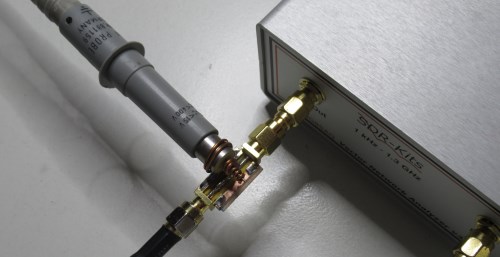
Then I set my signal generator at 20MHz and measured input and output voltage:
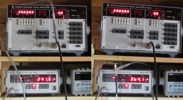
The measured impedance at 20MHz is 18.590 -j36.952; on that impedance, a voltage of 241.5mVRMS amounts to 0.634mWRMS (-1.981dBm); the output voltage is 364.1mVRMS on 270Ω, which is 0.491mWRMS (-3.092dBm).
The overall power lost in this cable at this frequency is 1.110dB, i.e. only 0.638dB more than the 0.472dB that this cable would have normally dissipated due to line attenuation. This is significantly different than the 2.779dB loss foreseen by the “Mismatch Loss” method.
Calculating mismatch losses
Is there a formula that allows us to estimate the loss of a mismatched transmission line? Yes, there is. You can find a complete explanation in the very interesting AC6LA’s site. These formulas require some parameters of the transmission line to be measured with a network analyzer. I measured my “Prospecta RG58” with two S11 runs (open/short) and I fed the S11 files to ZPLOT, which gave me back the nominal Zo, nominal VF, K0, K1 and K2 parameters for my line. I fed those parameters to the IZ2UUF Transmission Line calculator, which gave me the following results:
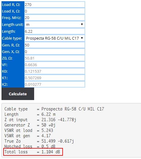
The software calculated a matched loss of 0.500dB (I measured 0.472dB) and a total loss of 1.104dB (I measured 1.110dB), which makes it a stunning “perfect match” with only 0.006dB of difference!
So far I got very good results comparing real and predicted loss figures up to VHF, with discrepancies of cents of dB. To test higher bands I shall do further work to cancel out the impact of measurement fixtures and probes.
Adding a tuner
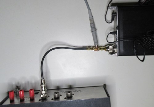
What happens if we add a tuner between the transmitter and the transmission line, as most hams do? In order to verify this, I connected the same 6.22m RG-58 line terminated with the 270Ω load to my MFJ-949E tuner and, with the help of my network analyzer, I tuned it to reach a perfect 50Ω match including the millivoltmeter probe:
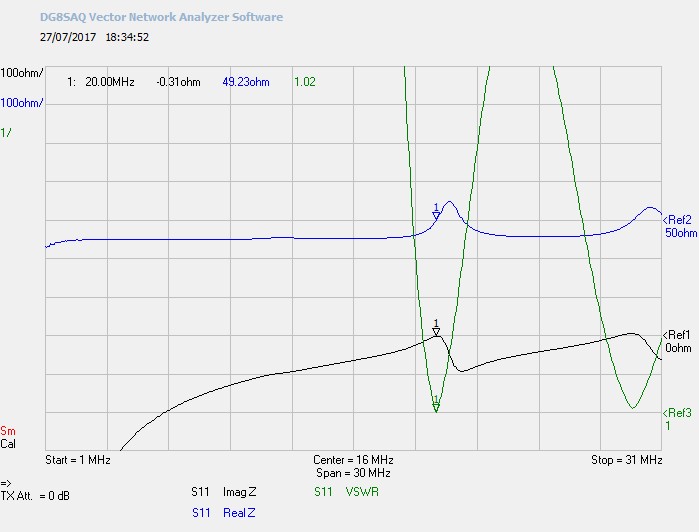
Then, I connected it to the signal generator and, using the RF millivoltmeter at the feed point of the tuner as a reference, I increased the generator power to compensate the extra cable I added. With 0.4dBm set on the signal generator, I had perfect 0dBm at the perfectly tuned 50Ω tuner input. As far as the signal generator is concerned, it is feeding a perfect load.
Let us see the voltage entering the line after the tuner and the voltage reaching the load:
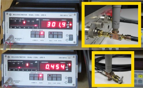
We have 301.9mV on the beginning of the line, where the impedance is 18.59-j36.952: solving the complex numbers calculation tells that my tuner is pumping on the line 0.990mW (-0.043dBm). At the end we have 0.454mV, which delivers to the 270+j0 load 0.763mW (-1.173dBm). This means that the line dissipated 1.130dB, which is almost identical to the 1.110dB measured in the previous example (difference is only 0.02dB!) and almost identical the 1.104dB calculated by the online calculator.
In these measurements we see that in this case the tuner received 0dBm and produced on its output -0.043dBm, thus dissipating as little as 0.043dB of power (<1%).
If we would have fed a perfectly matched 50Ω load with this 6.22m long RG58 line, we would have lost 0.472dB due to normal line attenuation. Feeding the same line with a VSWR>5 load and a tuner, we have lost 1.173dB, which means a net cost of only 0.701dB.
Be aware that such a low loss in a tuner is not a general rule, since tuning other impedances could cause greater heat dissipation, but it is very common.
Back to the Mismatch Loss
After all the experiments above, we have established beyond all reasonable doubt that the Mismatch Loss formula shown at the beginning of the article does not indicate the power lost when feeding a mismatched antenna. So, what is it for?
Let us consider these two simple circuits:
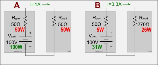
Picture “A” shows a 100V voltage generator with its internal 50Ω resistance Rgen feeding a 50Ω load Rload. Using Ohm’s law, we can calculate I=V/R=Vgen/(Rgen+Rload)=1A. Given that P=I2R, we can calculate the power dissipated by the load: Pload=I2Rload=50W. The generator itself is generating P=VgenI=100W and 50W are dissipated by the internal resistance Rgen.
Now we can do the same calculation on “B”, where Rload is 270Ω. We have that I = Vgen/(Rgen+Rload) = 100/(50+270)=0.3125A. Hence, the power consumed by the load is I2Rload=26.367W. The generator is generating P=VgenI=31.25W and Rgen is dissipating 4.883W.
We see that in circuit A the load is receiving more power: 50W vs. 26.367W: due to the maximum power transfer theorem, we get the maximum power (in this case 50W) when Rload=Rgen. For any other value, the power going to the load will be less. The “A” condition is defined as “matched“.
If we calculate the ratio of the power delivered on B and the maximum possible delivered power A, we have that 26.367 / 50 = 0.527; if we transform it in dB, we have 2.779dB which is exactly the Mismatch Loss we calculated before for the 270Ω load.
The Mismatch Loss value does not tell how much power is actually lost due to other dissipated, but it represents the inability of the generator to generate power due to mismatch.
Note also that the Mismatch Loss is not an index of efficiency: with matched load, we got the highest power on the load (50W) but efficiency was at 50% (100W produced, 50W used on the load). In the mismatched circuit, the generator produced 31.25W of which 26.367W were delivered to the load, holding an efficiency of 84.3%!
We can see this effect on the power that the R&S SMS2 signal generator has been able to deliver into the mismatched line with or without the tuner:
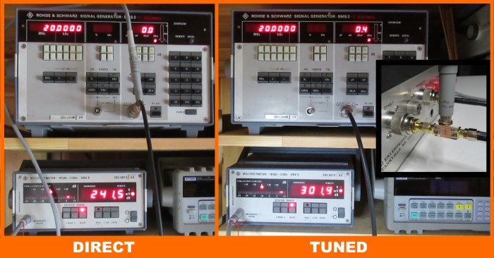
The difference in power between the two is 1.94dB: if we calculate the mismatch for the impedance being fed (note the reference impedance is 18.590 -j36.952 presented at the input of the line, not 270+j0 at load!), we have VSWR=4.3 and Mismatch Loss=2.13dB, again another almost perfect match to the measured values. Without the tuner, due to the mismatch, the signal generator was not able to generate the whole power it would have produced on a matched load: power is not lost, is simply not generated.
That is like when a biker is pedaling with the wrong gear: great effort, little performance. The tuner adapts the impedance at the input, exactly like the biker that shifts on the right gear.
Mismatch on real transceivers
Note that the mismatch effect that prevented the signal generator to generate the full power is mostly due to the fact that laboratory signal generators are designed to behave as close as possible as an ideal 50Ω generator. But being an ideal 50Ω generator, as we have seen, means low efficiency. Real transmitters are indeed designed to work on a 50Ω load, but not necessarily to present back 50Ω impedance when transmitting. Modern transceivers are able to compensate some degree of mismatch by feeding different voltages/currents to make the load happy. My FT-817 sends out the same power no matter of the load: changing the load, changes the voltage but the resulting power is almost the same until the HIGH VSWR protection kicks in by cutting the power. This kind of radio can feed mismatched lines within their VSWR tolerance without suffering loss of power, thus without the need of a tuner (I have planned to write another post reporting on this).
Conclusions
- the claim that a given VSWR values gives a fixed loss of power is a myth deriving from a misinterpretation of the concept of “Mismatch Loss”;
- if all the people that published such claim would have ever measured input and output power from a mismatched transmission lines, they would have immediately realized that true figures on power loss are most of the times very distant from their forecasts;
- the power lost in the transmission line is the result of a function that combines the mismatch and the normal loss of the line in matching conditions; an ideal (lossless) line would have no loss at all no matter of the VSWR;
- do not assume that feedline loss due to mismatch is always low: severe mismatches, like feeding a 40m 1/2 wave dipole on the 20m band, may cause very high losses in the transmission line;
- a transmission line is an impedance transformer;
- unless transmitting single bursts, the impedance of the transmitter has no relevance in the calculation of the power dissipated by the transmission line;
- the mismatch between the transmission line and the transmitter might prevent it to generate its maximum power but many transmitters might be able to compensate the mismatch;
- a tuner is not fooling the transceiver to believe the antenna is tuned, it is simply adapting two different impedances (after all, not many hams would describe their power supplies as objects fooling the radio to believe that the 220V AC power line is actually 13.8V DC, won’t they?);
- tuner is not wasting huge amounts of power as commonly believed: many times its insertion loss is negligible (tenths of dB) even with high VSWR.


This is great! I have been working on understanding this for at least a year, and this helped me greatly! Is there a downloadable/printable version I can add to my notes?
Hello Dave.
Thanks, I’m happy this work is helping out.
I’ve just added a “Printer Friendly” button that formats the pages for pretty printing; once you have pressed it, it has a feature to directly download it in PDF format. I hope it is ok.
Vy 73 de Davide IZ2UUF
Thanks David! I have printed the article and added it to my notebooks. The PDF looks great.
Your work is exactly what I was going to explore here, but I did not anticipate the single cycle vs continuous wave as being something to look at. Thanks for doing that discovery. I am working on understanding what you have done and I will try to duplicate it as much as possible with my meager gear to help me understand this further. You have certainly cleared up a number of questions I have had.
73!, Dave, KI4PSR
Wow.
Great! Mni tnx for this ufb article! Hopefully many HAMs will read it.
73, Hans, DK9NL
I need re-read and look into this in more detail but my first impression is that the lab work does not match the real world. For example, modern transceivers reduce power output based on mis-match. Also, is mismatched out of phase power getting back to the antenna load useful power? I suspect not. This is not to say that this is not a great article and good work. I just need to digest it more.
Hello James and thanks for your comment.
Modern transceivers reduce their power when the mismatch goes above a limit defined by the constructor. You can simply match the transceiver to the impedance presented by the transmission line by mean of a tuner and you got rid of this variable.
However, this is not the point of this article. The goal of this article is to show that the so called “mismatch loss”, a value that comes from direct calculation from the reflection coefficient, is not meant to estimate a loss due to VSWR of an antenna. I often have seen HAMs explaining that “after all, a VSWR of 3 causes a mismatch loss of only 1.256dB so…” – well, that is not true, the mismatch loss doesn’t mean that.
You can also answer yourself to your question “is mismatched out of phase power getting back to the antenna load useful power” by considering perfect components.
Take a circuit made of a perfect 50 ohm generator, a tuner made of a pure L and a pure C, followed by a transmission line made of perfect conductor terminated to a non purely reactive load (i.e. something having R!=0 and whatever X you like).
Being all perfect, there is no mismatch between the generator and the tuner, so all the power from the generator is to be transferred to the tuner (otherwise it wouldn’t be a perfect match).
From now on, this power goes through a perfect LC circuit (the tuner) which being purely reactive, can not dissipate any power. Then it goes into a trasnmission line, which has no resistance so it can not disspate power as well. The only element that can consume power is the “R” of the terminating load, the antenna. It doesn’t matter whether the load is reactive or not: there is no alternative, otherwise you would break the law of conservation of energy.
In my examples I haven’t used reactive loads because the explanation would have required more calculations with complex numbers making the article even harder to follow.
Coming down to real “unperfect” world, it becomes just a matter of how far from perfection are the components we are using. Starting from a given antenna with a given R, X impedance, the power lost from the transmitter to the antenna is a matter of how much resistance each component has and how much current goes on it: I think it is obvious now that the loss due to mismatch can’t be a fixed “mismatch loss” number.
Vy73 de Davide IZ2UUF
I agree that most hams do not understand SWR and good practice for that matter. I spoke with a new have this last week who was using 100ft of RG-6 between the output of a 2-meter rig and a standard 2-m antenna. Your scholarly work will not be understood by most people and may be interpreted by some as justification for something like my example above. An example of the need for perfect matching. In the GE Mastr II repeaters GE was having trouble losing the PA. Investigation revealed that duplexers were not tuned properly. As you know, a misaligned duplexer can cause a severe mismatch. GE produced a small matching network to be inserted between the PA and the duplexer. In my opinion this was not the proper solution but it was financially expedient for GE and the customers did not know any better. My only problem is the misunderstanding by some (if not many) hams.
Grande Davide! Neanche le pagine dei blasonati testi anglosassoni sull’argomento chiariscono la questione come hai fatto tu! Orgoglioso che tu sia italiano. 73 de IZ7VHF.
Thank you very much indeed, Davide! I have read a lot of pages on famous american ARRL books but you article is better clarifying the matter! I’m proud you are italian like me!
I have looked this over in detail and strongly disagree with the conclusions. A lot of effort was put into the testing but the author is confused about conservation of power (energy) and getting useful power to the antenna. The key is useful power. Useful power is not mismatched. A mismatch impedes the efficient transfer of power from the radio to the antenna. A rhetorical question – what happens when two phases of a sine wave reach the antenna? – Is there cancellation – is there heating? We know that mismatched power is harmful – there a few of us who have not destroyed the driver or final of a transmitter with a mismatched load. This is the reason that transmitter manufacturers now reduce output power based on a sensed mismatch.
This appears to be one of those articles that trolls know facts. You can find articles that state “grounding is bad – never do it”. If we were to accept this author’s conclusions then we can assume that good practice is irrelevant. Just recently, I was thinking of ways to use the word “resistance” in a humorous way and came up with a truism that has nothing to do with “electrical” resistance.
“The path of least resistance doesn’t radiate well”.
Throwing together a transmission line and antenna system without regard for the best matching possible is simply wrong and it won’t work well. This author would have us believe that good practice is irrelevant – it is not.
Hello James.
Your comment looks a bit confused: are you sure you are referring to this article and not some others?
The thesis is: “the claim that a given VSWR values gives a FIXED loss of power is a myth”.
This article is not concluding nor even insinuating that good matching is not relevant in an antenna system: it is showing that the mismatch loss formula, that associates a given VSWR to a fixed, immutable, absoute loss in dB, is not the one to be used to evaluate losses in a mismatched antenna system.
You can disagree with the conclusions of this article if you can prove that no matter how the system is designed, an antenna presenting VSWR=3 causes always a fixed loss of 1.256dB.
Please, stay on topic and do not insinuate conclusions I haven’t drawn.
Thanks
Hi Dave,
Seldom, I enter into discussions on the web. Because of your well-done reporting of your cable tests, I make an exception.
In the end, we want to know how much of the maximum available power from the transmitter is getting at the end of the cable into the mismatched antenna. Right? Therefore, let’s go to the end of the cable and do some basic measurements there.
I suggest the following simple test (continuous sinusoidal signal from the generator). For the case of 50 Ohm generator output impedance and your RG-58 cable with characteristic impedance of also 50 Ohm (i.e., matching at generator side) please perform (or consider if already done) two measurements as follows:
Test-1: Connect the 50 Ohm load resistor to the end of the cable (i.e. matching also at end of cable) and measure the peak voltage across this load. Calculate by hand the dissipated power by (U^2/(2R)) with U for the measured peak amplitude and with R=50 Ohm.
Test-2: Only replace the 50 Ohm resistor by the 270 Ohm resistor and do the same measurement again at the end of the cable i.e. at the resistor, and calculate the power again by hand for R=270 Ohm.
Question #1: How do the two calculated power values relate to each other and in comparison to the VSWR mismatch equation that you present at the very start of your discussion?
Question #2: Do you think the found ratio of the two power values would change if we change the length of the cable and therefore the cable loss? And what would change if we do Test-1 and Test-2 right at the generator output without any cable?
After your findings, we can discuss further.
Cheers,
Alice
Hello Alice.
Thanks for commenting on my blog.
– Right.
I shall immediately do one of the experiments you are proposing. I’ll take my FT817ND and have it transmit in a 33Ω load and in a 110Ω one. Here it is the picture:
The first test puts 4.33Vrms across 33.938Ω, giving 552.44mW. The second test puts 7.91Vrms across 110.247Ω, giving a power of 567.53mW. But… wait a minute! The 33.9Ω gives a VSWR of 1.475, 110.2Ω gives a VSWR of 2.204, but the power delivered on the 110.2Ω load is 15.09mW higher! From this test, should I conclude that the higher is the mismatch, the more power is delivered to the load? Or not?
Your line of approach is flawed by the fact that with the load directly connected to the generator, you are just challenging its ability to cope with mismatched loads. A laboratory generator will try to behave as an ideal fixed output impedance generator, a real RTX won’t. Furthermore, no ham operator will ever feed a line with VSWR 5.4 (so much is a 270Ω load), without placing a matching network (i.e. a tuner) between the RTX output and the line. At this point the issue becomes about how much power is dissipated by the tuner: you can’t think that the losses within a matching network done with cheap SMD inductors would be the same of one made of superconductors.
The test of measuring only the power at the end of a line with different loads or line lengths is also flawed. You will never know how much is the power lost by the line and the power fluctuation due to the generator coping with the changing mismatch.
Even the test of comparing the power delivered directly to a 270Ω load with the power delivered to the same load at the end of a feed line is flawed. If you put a 270Ω resistor at the end of a line, you don’t get an impedance of 270Ω+j0 at the feeding point unless the line is ideal and half wavelength long. On a real line you do not even get the same mismatch (i.e. the same VSWR), because the longer the line, the closer the feed impedance is to the line characteristic impedance. A very long line will look as a load with pratically the same impedance of the characteristic one of the line no matter what the load at the end is.
So, you connect a 270Ω load at the end of a 6m long line and at the end of a 20m long one of the same type. You measure the delivered power and what you get? You get a value that is the combination of the power lost by the line and the different power delivered by the generator due to different impedances on its output. Since you will never be able to tell which is which, the test would be meaningless.
The only way to determine the power lost by the line is to measure the power entering and the power exiting at the same time.
If you want to know how much power is delivered to your antenna, you have to calculate the power lost by the line due to the mismatch at load. Then you have to calculate the power you loose in the attempt of feeding the impedance of the line presented at the feed point. This means measuring the power that your own RTX is actually able to deliver on that mismatch if you connect it directly to the line. Otherwise, you will have to calculate the power dissipated by the matching network if you go for this route. Furthermore, not many ham RTX are able to feed a 270Ω load (VSWR 5.4) without having the high-SWR protection kicking in, so feeding directly without a matching network is not even an option.
In this scenario, the Mismatch Loss formula cited at the beginning, which wrong application is the topic of this article, gives no clue at all on how much power will be delivered to the load.
Vy73 de Davide IZ2UUF
This is my final contribution to this forum.
You write:
“You can find a complete explanation in the very interesting AC6LA’s site.” But apparently you did not notice the title of that web site: “”Additional Loss Due to SWR” is in Quotes for a Reason”.
For very good reasons, Dan Maguire actually doubts the equations that have been ventilated by the ARRL since tens of years and which you seem to refer to in your discussion. Perhaps you believe in, or are a victim of, the hoax science of Re-Reflection by R. Walter Maxwell (1919-2012).
I have been in contact with Dan. It is all related to the ratio (Pin/Pout) for which you advocate regarding measurements but apparently without carefully realizing what Pin actually is. Perhaps ask yourself why the notorious VSWR discussion and confusion is circulating for tens of years in the ham radio area while such mess does not exist in the professional RF and microwave area and not in university textbooks. But perhaps all that stuff is also flawed except your very own way of thinking and measurements in your ham radio lab.
Cheers, and take care.
Hello Alice.
Thanks for your final contribution to this forum.
However, your conclusion is once again flawed: I’m not referring at all to the equations ventilated by ARRL nor those published by W2DU W. Maxwell.
I’m using AC6LA’s formulas which had proven accurate under lab measurement at the conditions I have published. I even published an online calculator using them (it is linked in the article).
Al PIN/POUT measurements have been done by measuring the complex impedance and voltage on the input of the line and the load and applying Ohm’s law in complex form. The difference must be the power dissipated by the line, otherwise you’ll break the law of Conservation of Energy. The resulting data match the power loss estimated by AC6LA calculator within 0.06dB as you can see from the pictures below:
It would be nice if discussions would be based on what is actually written and not on what is “supposed” by the readers. Your first comment was based on flawed lab tests. Your second comment was based on wrong assumptions. On which basis shall we discuss? If you wish to be taken seriously, you should make sure at least to show that you thoroughly understood what you are talking about, including what I have written in this post.
Vy73 de Davide IZ2UUF
My really final contribution to this Blog and to your readers:
From your Experiment 1 (50 Ohm matched Generator; 50 Ohm matched load), Continuous Stream of Sinewaves, the displayed amplitude of the voltage across the R=50 Ohm load is 1.12V pk. Therefore, the peak power (U^2)/R delivered to this R=50 Ohm resistor, is 25.09 mW. (Readers of this blog can easily check the calculated numbers, if in any doubt.)
From your Experiment 4 (50 Ohm matched Generator; 270 Ohm load), Continuous Stream of Sinewaves, the displayed amplitude of the voltage across the R=270 Ohm load is 1.86V pk. Therefore, the peak power (U^2)/R delivered to this R=270 Ohm resistor, is 12.81 mW.
The VSWR implied by the 270 Ohm resistor is 5.4, which implies as per the ML formula that you criticize, a Mismatch Loss of 2.8 dB.
The ratio of the above two power values (at load) of 25.09 mW and 12.81 mW is 10*log(25.09/12.81)=2.92 dB. Bingo!! That is quite a good match with the 2.8 dB predicted from the ML formula, isn’t it! You and your blog readers would obtain the same ratio of 2.92 dB not only for your chosen 24.9 m long cable but also for another chosen cable of different length and, thus, different cable attenuation. If anybody does not believe this, s/he should just try it out!
In Experiment 1 (matched case of 50 Ohm on both sides), you report a loss of 1.02 dB for the given 24.9 m cable etc. at 5 MHz. –
In Experiment 2 you report the 1.26 V output of the Generator corresponds to 31.75 mW peak power on 50 Ohm. This represents the maximum power Pmax for your chosen Generator setting and available under matched conditions.
Therefore, in the case of the 270 Ohm resistor (50 Ohm Generator) the total loss relative to the maximum power available (the Transducer Power Loss), is 10*log(31.75/12.81)=3.94 dB – which perfectly equals the sum of the measured 2.92 dB (Mismatch Loss) plus the cable loss of 1.02 dB.
In fact, your very own measurements confirm the validity of the ML equation and the total loss calculation which you attempted to question.
HAM Radio guys are interested to know how much of the available maximum power Pmax gets via the feedline into the mismatched antenna – and you confirmed this objective in your first reply. The corresponding loss is the Transducer Power Loss. From your measurement principle of determining P1 at cable input and P2 at cable output it seems you should think about what the input power P1 of the cable actually is in case of mismatch at the end of the feedline. For a lossless line, the two power values P1 and P2 at the input and output of the cable are obviously identical. But this in no way means, or implies, that the output power of the cable would be Pmax regardless of the mismatch or VSWR. In fact, the reflected power is returning along the lossless line and eventually into the generator that with its output impedance of 50 Ohm is matched to the cable characteristic impedance. Therefore, this reflected power is a loss regarding the transfer of power between generator and load, because this part out of Pmax has been reflected and, thus, has not been delivered to the load.
Your statement “an ideal (lossless) line would have no loss at all no matter of the VSWR” is obviously true from a cable-loss point-of-view. However, it is seriously flawed from the point-of-view of the Transducer Power Loss which actually matters for the power transfer between generator and the mismatched load. In fact, for a lossless cable the total loss (or Transducer Power Loss) equals the Mismatch Loss as per the ML formula. (For the case of mismatches both at load and at the generator side, the equations are more complicated.)
Dan Maguire (AC6LA) is informed about the problem in ARRL handbooks and his program TLDetails regarding loss calculations. He understands the issue, and on 15 Dec he replied:
“That was a very thoughtful email. Thanks for taking the time to compose your thoughts. …
>>> Therefore, I suggest revising the TLD tool by applying the change outlined above.
At the moment I am swamped with antenna modeling work. If I ever get back to TLDetails I will indeed consider your suggestion.” (end of quote).
In conclusion, your own measurements do confirm the correctness and applicability of the approach and the equation that you attempted to put in question. In fact, your measurements confirm the inadequacy of some (ARRL) material and the loss calculator in the TLDetails tool about which AC6LA is aware. Finally, the findings from your carefully conducted measurements are in line with established professional RF and microwave techniques and reference books and material. You, like many others, apparently got trapped by flawed and misleading (ARRL) reference material imposing wrong interpretations of (P1/P2) and in consequence questioning the establsihed Mismatch Loss equation.
The Myth is not the ML equation from hundreds of professional RF reference books regarding mismatch loss; the real Myth is some dodgy widespread material about alleged “Total Loss” and the implied confusion.
Cheers.
Thanks Alice for your really final contribution to this blog.
However it seems once again that you are completely missing the point of this article.
I’ll try to make it straighforward.
Claim found on a ham forum on the internet: this antenna presents VSWR=6 [in a 50Ω system], thus we shall loose 3.1dB of power [due to mismatch loss].
My claim: true only if you are feeding it directly with an ideal 50Ω generator; if your are using a normal sequence made of RTX, tuner, coax this value can be much different
If you use an ideal matching network and an ideal line, your power loss is zero no matter of the mismatch. Proof: the generator is perfectly matched due to the perfect matching network; no components other than the load, being ideal, have resistive parts thus none can dissipate any power.
If you use a real matching network and a real transmission line, it depends on the characteristics of such lines. Proof: my experiment titled “Adding a tuner” shows a chain made of a 50Ω lab signal generator, a tuner, a 50Ω tranmssion line and 270Ω load. The generator is set to 0dBm; the power reaching the input of the tuner, which presents impedance 50+j0, is -0.043dBm, i.e. ~0dBm as expected. The power reaching the 270Ω load is -1.173dBm, which is far less than the -2.779dB forecasted by the mismatch formula.
By the way, your sentence In fact, for a lossless cable the total loss (or Transducer Power Loss) equals the Mismatch Loss as per the ML formula. is like a contradiction in terms. A “lossless cable” is a cable that has no losses, i.e. it has no resistive component able to dissipate power as heat nor shielding imperfections able to radiate power as RF. Therefore, there is no way you can apply 1W to the input of the cable and have other than 1W delivered to the load no matter what the load is, otherwise you’ll break the law of conservation of energy. Otherwise, where the extra energy is supposed to be dissipated if the cable is lossless? You can have less power delivered only if the generator is able to pump less power into the line due to the mismatch – but this is not being negated by me anywhere in this article nor anywhere else and I keep wondering why you are insisting on this.
Reading the rest of your stament For the case of mismatches both at load and at the generator side, the equations are more complicated it is clear that you mean In fact, for a lossless cable [fed by a matched generator] the total loss (or Transducer Power Loss) equals the Mismatch Loss as per the ML formula. A generator is matched when its impedance is the conjugate of the impedance of its load, which is the transmission line input in this case, not a generator which has the same impedance of the characteristic impedance of the line – and on a lossless line, this means 0dB loss, not the ML. If your generator has the same impedance of the characteristic impedance of the line, on a lossless line it will deliver a power reduced by the mismatch loss as the load was connected without transmission line, but this is not something I have ever denied (I even added a chapter titled “Back to the Mismatch Loss” where the ML formula was explained.
If you wish to dispute the point of this article, you should challenge the point of this article: you should demonstrate that no matter what you do (add tuners, change transmission lines, etc.), the power delivered to a mismatched load would suffer always a loss of no less than the mismatch loss. I have shown in this article an experiment where a 50Ω lab generator set to 0dBm, through a chain of passive components, delivers -1.173dBm on a 270Ω load, which is 1.6dB more than the -2.779dB forecasted by the mismatch loss formula: to challenge the point of this article, you should also prove that this experiment is fake.
Looking forward for your really final-final contribution to this blog, I wish you my best 73s.
Davide
For those who believe the reflected energy is dissipated by the generator I propose the following: connect your generator of choice to in infinitely short transmission line with an open at the end. How much power is the generator dissipating? Now short the transmission line. Now how much energy is being dissipated? Conclusion, you can’t talk about what happens to the energy without knowing details about the generator and the phase of the reflected wave.
This is the best combination of analysis back with experiment to this issue of reflected RF on a transmission line that I’ve come across. I’ve struggled with competing arguments (like those expressed by Walter Maxwell and others) for quite a well, your article illuminates the mechanics a bit more clearly. Thank you for taking the time to publish.
I see you don’t monetize iz2uuf.net, don’t waste your traffic, you can earn extra bucks every month
with new monetization method. This is the best adsense alternative for any type of website (they approve all websites), for more info simply search in gooogle: murgrabia’s tools
After reading and re-reading your article, I started to understand what you’re trying to point out. But when I read Alice’s posts, I was inclined to agree with her logic, which seemed to make complete sense. That, in turn, made me take your article apart and dissect it piece by painfully slow piece, until I had to conclude that you are absolutely correct in both your logic and your calculations, confirmed by your lab work. It’s clear now that, while Alice is not completely wrong in her assertions (the “Mismatched Loss Equation” is valid), she seemed to have missed the point of your article (the “Mismatched Loss Equation” does not mean that a fixed VSWR will result in a fixed loss of power). Thank you for taking the time and effort to put this together, and busting yet another myth.
I do not see a reason based on physics, why a pulse would behave differently than a continuous wave, when returning from the mismatched load to the mismatched generator.
This is a weak point in that essay.
Placing a temperature probe on the resistors would clarify the situation, alternatively use a thermo camera and watch the antenna feeding lines and the smoke from the transmitter finals 🙂
I think: A single pulse will not demonstrate the total sum of the source and reflection, as the delay in transmission lines puts them out of phase. We need the full 360 of each waveform to overlap for accurate math. I suppose we could consider an instantaneous sum if it is a pure sine….and we know the angle?
Great work. I would love to see how this looks when using window line on high vswr with same conditions. K4kfi
Sorry I wore out after the second paragraph.
Nice job! Us older hams have always know that a high VSWR only increases the cable loss and that a 5:1 VSWR doesn’t really mean that 50% of the power is lost. I believe the confusion comes from defining the output impedance of a power amplifier. Take a typical MOSFET amplifier where the matching transformwe is use to match the “2 ohm output impedance” to 50 ohms. This impedance isn’t the classical definition of output impedance, but rather the impedance that produces maximum power based on the power supply voltage and maximum current of the devices. The actual output impedance is about 10 times higher (it’s a current source). So matching is this case refers to presenting an impedance to the amplifier that maximizes its output power regardless of the VSWR.
I haven’t ever come across an RF amplifier that is designed for maximum power transfer rather than maximum efficiency. They aren’t the same.
Hi Davide,
What a brilliant demonstration, congratulations !
73, Olivier F1ETJ
So operating at 100 watts, what is the safe range for reflected power numbers?
Regards,
Rich
I was doing my research on a talk I was giving to the local ham club. Mostly new hams. Your article brought me new ideas for my talk. One sure thing I am going to mention-the tuner in line does not have any real loss compared to what it does. I have the same tuner. K5SL
Thank you so much, as I have been telling people for a long time that matching both ends of a coax cable with a tuner regardless of the used feedline has little losses. This confirms again that coax attenuation is an importantfactor and should not be taken for granted because it’s HF. I for one tune always, no matter what the SWR-meter tells me it should be. And 1:1 is not something I go after, as it’s impossible with a multiband like the G5RV.
First, Ive been a ham for 63 years, but I’m a technical dummy with only basic knowledge of this science. However I totally enjoyed the debate with Alice. From her name, I assume she identifies as a woman. That actually make no difference to the argument at hand, but her attitude certainly correlates to a stereotype with which I am familiar.
How about this experiment? place a 50ohm load at the end of an electrical half wavelength of 450 ohm Ladder line. The generator will see very close to 50 ohms therefore dump 100w power in. The SWR at the 50ohm Dummy load will be 9:1. or 64% reflected. How much power is dissipated in the 50 ohm load? My guess would be about 95w. not 36w.I Think Alice would expect 36w !!
A little of the subject but, you make the statement that “In other words, the reflections change the impedance of the transmission line at the feed point.” I believe this will cause a reflection at the source end of the transmission line as the there is no longer a perfect match at this location. So will we have a reflection at the load end of the line as well as the source end if the line or the incipient wave, the wave from the generator. I base my thinking on the coefficient of reflection at both ends of the line. Thank you
Your work is a pleasure to read. You might drive this home using the 1/2wl 600r TLT using a 50r load. The combined incident and reflected current is the same as that of the matched 50r load. The loss is far more significant using coax than the OWL 600r line.