
Most ham operators know that by combining inductors and capacitors in various configurations, they can tune their antenna impedance to match their transceiver. Many people, due to their experience, can also estimate the µH and pF ranges they need to tune on the various bands.
But, what is the basic principle that actually allows a tuner to tune? And is it true that the power reflected by the mismatched load is dissipated by the tuner?
A real-world experiment
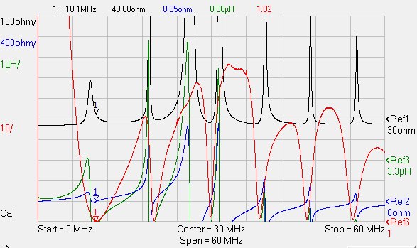
To have something real to work with, I prepared a test load by connecting in series three 8Ω-5W badly inductive resistors, thus presenting both some resistance and some reactance, as it is usual when tuning antennae. I selected an operating frequence of 10.100MHz and connected the test load to my newtork analyzer to see how it looked like:
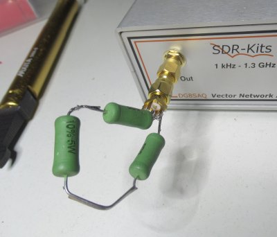
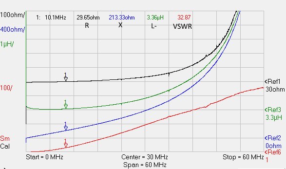
The response of the VNA shows that at 10.100MHz, this load shows R=29.65Ω, X=213.33Ω, the inductance of the resistors is 3.36µH and the VSWR of this load is quite high, 32.87:
To tune this load I selected a simple Hi-pass, step-up L tuner layout:
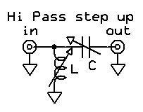
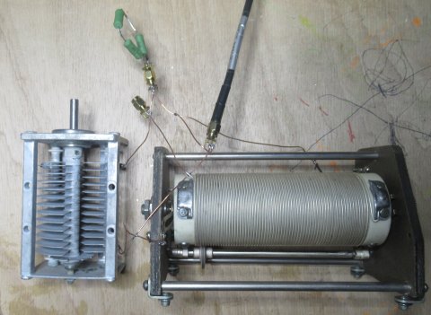
Using a roller inductor and a big variable capacitor I created my L-tuner and I tuned the test load at 10.100MHz using my network analyzer to measure the resulting VSWR:
By carefully setting the knobs, I have been able to tune a perfect match with R=49.8Ω, X=0.05Ω and VSWR=1.02:
So far, so good.
Measuring the components
Next step is to measure the inductance of the inductor and the capacitance of the capacitor:
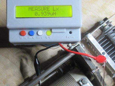
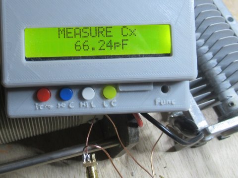
We have that C=66.24pF and L=0.939µH. Why are these exact values able to tune our load?
The magic of circuits
The principle that allows a tuner to “tune” is the same of the trick that every electronic technician, even beginners, use to “create” resistor values by combining other resistors in series or parallel.
Let’s take two resistors, R1 and R2:
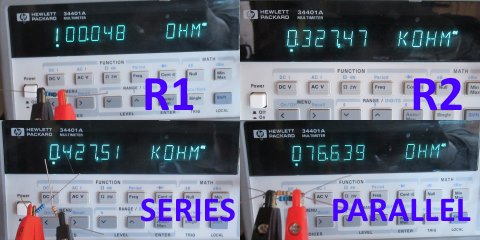
We have R1=100.048Ω and R2=327.47Ω.
If we combine them in series, we have that [1] Rs=R1+R2=427.518Ω, confirmed by the measurement of 427.51Ω.
If we combine them in parallel, we have that [2] Rp=1/((1/R1) + (1/R2))=76.635Ω that is also confirmed by the measurement (76.639Ω). The operation 1/x is called the reciprocal of x, so [2] can be expressed as the reciprocal of the sum of the reciprocal of each resistance.
From resistance to impedance
The resistance case seen above is just a special DC case of more general AC concept called impedance. The impedance describes a component in terms of resistance and reactance that show at a given frequency; if the frequency is 0Hz, we have back the “DC” case.
When we measure an aerial with our antenna analyzer, we can read on the display the resistance (R) and the reactance (X) which form the impedance of that object at the measurement frequency.
It is important to underline that the impedance is always formed by two numbers: R and X. When people use a single number for the impedance, there is always something implied: for example, when people talk of a “50Ω antenna”, they mean “a R=50Ω X=0Ω antenna” where “X=0Ω” is implied.
The impedance pair of vaules R,X describes an equivalent circuit made of an ideal resistor of resistance R in series with a capacitor (if X is negative) or an inductor (if X is positive). If X is zero, the impedance is equivalent to a simple resistor and it is defined resonant.
How do we calculate the “X” reactance?
While the “R” value of the impedance is simply series resistance in Ω of the object being measured, the “X” value is a bit more complicated. Its value depends on the capacitance (if negative) or the inductance (if positive) and the frequency according to the formulae below:
In case of inductive reactance, we have: X=2π·f·L
In case of capacitive reactance, we have: X=-1 / 2π·f·C
Where:
- f is the frequency in MHz
- C is the capacitance in µF
- L is the inductance in µH
- π is 3.14159
Now, we shall calculate the impedance of the inductor and the capacitor of our tuner.
The inductor was L=0.939µH; at 10.1MHz its reactance would be X=2π·10.1MHz·0.939µH=59.589Ω. Our inductor is not ideal but shows also a series resistance of about 1Ω. Therefore, the impedance of our tuner inductor is:
ZL: 0.939µH@10.1MHz → RL=1Ω, XL=59.589Ω
Now we can calculate the same value for our capacitor that measured C=66.24pF=0.00006624µF (remember that we are using MHz and µF: do not use pF!). We have X=-1/2π·10.1MHz·0.00006624µF=-237.891Ω. Capacitors like mine have negligible series resistance (ESR) so we can safely take 0Ω:
ZC: 66.24pF@10.1MHz → RC=0Ω, XC=-237.891Ω
The tuned circuit
Our tuned circuit now has three components: the load (i.e. the antenna or whatever we connected at the tuner output) plus the capacitor and the inductor of the tuner. We also know exactly the R,X impedance of each of them.
They are configured in this circuit, where ZA is the antenna or our load, ZC is the capacitor and ZL is the inductor:
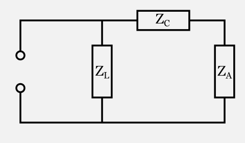
The first thing we notice is that ZC (the tuner capacitor) and ZA (the load on the “antenna” port) are in series:
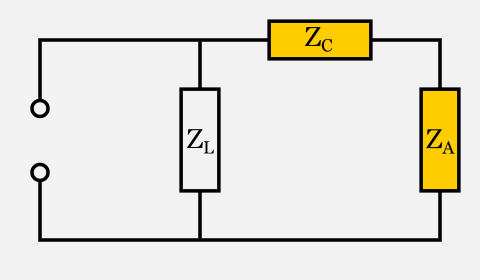
If they were simple resistors, we would know how to replace them with a simple equivalent component (another resistor): by would simply add them.
The interesting fact is that also impedances can be replaced by a third impedance which is the sum of the other two. The new impedance ZB=ZC+ZA will be made of two components, RB and XB, calculated as follows:
RB = RC + RA = 0Ω + 29.65Ω = 29.65Ω
XB = XC + XA = -237.891Ω + 213.33Ω = -24.561Ω
Thus we can replace ZC and ZA in series with a single impedance ZB having RB = 29.65Ω and XB = -24.561Ω and obtain the following equivalent circuit:
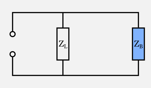
Now we have left two components in parallel: what is their combined impedance?
The formula for parallel resistances [2] suggests that we should calculate the reciprocal of ZL and ZB, sum them together and then calculate the reciprocal of the resulting value. But how do we calculate the reciprocal of an impedance, which is formed by two values R and X?
The reciprocal values R’ and X’ of a given impedance R, X is to be calculated as follows:
R’ = R/(R2+X2)
X’ = -X/(R2+X2)
So let’s start calculating the reciprocal of ZL:
RL‘ = RL/(RL2+XL2) = 1/(12+59.5892) = 0.00028154
XL‘ = -XL/(RL2+XL2) = -59.589/(12+59.5892) = -0.0167769
Now we can calculate the reciprocal of ZB:
RB‘ = RB/(RB2+XB2) = 29.65/(29.652+(-24.561)2) = 0.020002
XB‘ = -XB/(RB2+XB2) = -(-24.561)/(29.652+(-24.561)2) = 0.016569
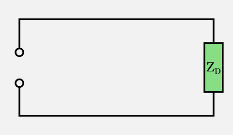
Now, according to formula [2], we have to add those values together and calculate once more the reciprocal to obtain ZD:
We first calculate ZD‘:
RD‘ = RL‘ + RB‘ = 0.00028154 + 0.020002 = 0.02028354
XD‘ = XL‘ + XB‘ = -0.0167769 + 0.016569 = -0.0002079
Then we have to calculate the reciprocal of ZD‘ to obtain ZD and the “magic” is completed:
RD = RD‘/(RD‘2+XD‘2) = 0.02028354/(0.020283542+(-0.0002079)2) = 49.2959
XD = -XD‘/(RD‘2+XD‘2) = 0.0002079/(0.020283542+(-0.0002079)2) = 0.5053
The final impedance of the entire circuit is R=49.2959Ω X=0.5053Ω is almost a perfect match for the target impedance of R=50Ω X=0Ω and very close to the measured value of R=49.8Ω, X=0.05Ω.
Power lost in the tuner
How much power is actually “lost” in the tuner? Power can only be dissipated by the resistive part of the impedance. If we could make a tuner with ideal capacitors and inductors (i.e. purely reactive), the power dissipated by the tuner would be none.
The power actually dissipated by each component can be calculated with the same basic circuit rules that allows us to calculate the power dissipated by each resistor in a resistor network. However, usually the resistance of the tuner components is not high enough to cause significant losses in the tuner itself in most tuning cases.
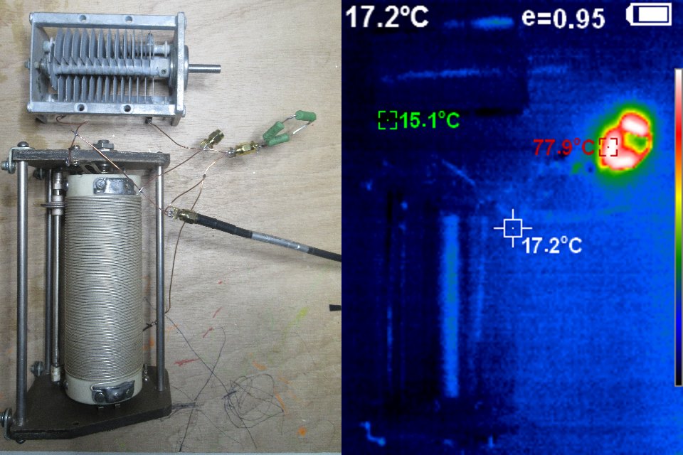
This fact is clearly shown by my tuner in action under a thermal camera: as we can see, only the load resistors are hot while the tuner components are not dissipating any relevant heat.
Conclusions
A tuner is able to transform the impedance of the load into the impedance required by the generator by creating a circuit that, combined in series/parallel with the load, adds up to the required impedance. Since the components added by the tuner are reactive, no power is dissipated by an ideal tuner and all power is trasferred to the load. Real tuners are designed to have very low loss components, so usually almost 100% of the power actually reaches the load.
Notice
This is an article about how a tuner does the tuning process and it efficiency, not about what a load does of the energy it received.
If you connect a transmission line between your tuner and a mismatched antenna, the trasmission line will dissipate more power than usual, sometimes a lot of power: in this case, blame the transmission line, not the tuner. To know more about transmission lines on mismatched loads, please refer to The myth of reflected power.

Finalmente ho capito come funziona un accordatore. Prima mi sembrava qualcosa di magico, che in trasmissione non facesse passare la corrente riflessa verso l’rtx, mentre in ricezione ne coadiuvasse il transito. Cosa ovviamente impossibile. Quindi quello dhe prima mi appariva come una sorta di diodo nella sola trasmissione ora non ha più veli. Eppure ne ho cercata di documentazione per capirci qualcosa. Once again, grazie Davide.
“Since the components added by the tuner are reactive, no power is dissipated by an ideal tuner and all power is trasferred to the load.” — That’s true if you consider the load to be the coax attached to the output of the tuner or if the tuner is located at the antenna input.
But if the antenna is not a perfect match to the coax, power is dissipated by the coax.
Yes, that’s true. However, this is an article on tuners, not transmission lines.
Each component has its own role in transferring the energy and we can not blame the tuner for the energy dissipated by the transmission line.
I already treated the argument of energy dissipated by mismatched transmission lines here: The myth of reflected power
Good article, thanks. Antenna turners do work and will result in getting more power into the antenna/radiator. What the antenna does with this power is another issue. But the article addresses how to get the match between the radio and load/antenna system.
Does an antenna tuner , if tune properly, actually result in more RF power being radiated by the antenna? I still find this confusing. I like you explanation of how it works but does it indeed mean you can transmit further than you could without the tuner with a non resonance antenna?
THIS “ANTENNA TUNER” IS NOT THE PROPER TERM FOR A DEVICE THAT MATCHES A SOURCE TO A LOAD. WE KNOW THAT WHEN Z SOURCE = Z LOAD, MAX. POWER TRANSFER OCCURS. WE DONT TUNE AN ANTENNA, MORE ACCURATELY, WE MATCH THE IMPEDANCE OF THE ANTENNA “SYSTEM”. EVERYTHING BETWEEN THE SO-239 TO THE ANTENNA. A BETTER TERM FOR THESE IS, ANTENNA COUPLER, MATCHBOX,TRANSMATCH, ANYTHING BUT TUNER.. CUT A 65’ DIPOLE AND YOU HAVE TUNED IT TO 7.2 MHZ. THE OMLY WAY TO TUNE, RETUNE, DETUNE, MISTUNE AN ANTENNA IS TO ALTER THE PHYSICAL DIMENSIONS OF THE RADIATING (DRIVEN) ELEMENT. MAKE THAT DIPOLE’S LENGTH 65’ 11”. AND IT IS TUNED TO 7.1 MHZ. THE BOX ON YOUR DESK SAYING ANTENNA TUNER CANT DO THAT. AN “AUTO TUNER” CANT EITHER. WHEN YOU CHANGED THE LENGTH OF YOUR RADIATING ELEMENT (DIPOLE), YOU TUNED IT. THE JOB OF MATCHING SOURCE TO LOAD IMPEDANCE IS WHAT IS PERFORMED BY AN ANTENNA TUNER, A TRANSMATCH, COUPLER ETC. THERE IS NO MAGIC, JUST EQUALIZING THE REACTANCES AS BEST AS POSSIBLE TO A NET ZERO. THATS IT.