Today I wanted to measure the characteristic impedance of a unknown transmission line; in this case, it was a Hi-Fi stereo line I bought from the local hardware store.
Measuring the impedance with miniVNA is quite simple: as we know, when a transmission line is correctly loaded, it should return a fixed resistance value and no reactance, no matter of what frequency we are using.
Therefore, my idea was to put a variable resistor at the end of the line (in this case 4m long) and try to get the flattest response as possible.
This is the setup:
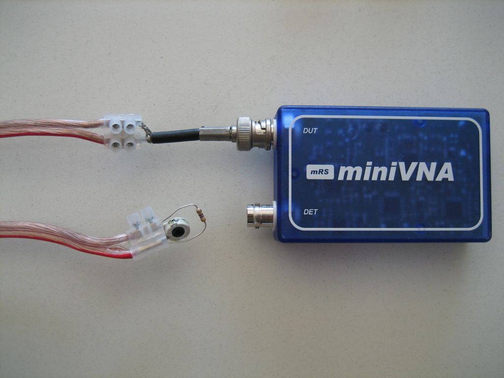
I used a 2.2K trimmer with a 470K resistor in parallel to lower the range.
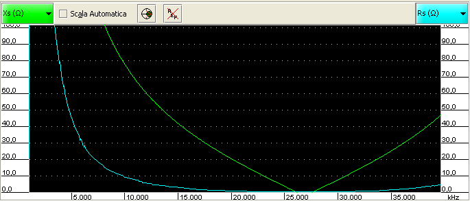
This is the result with a badly regulated trimmer:
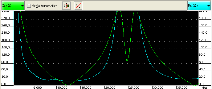
As we can see, the reactance and resistance change very heavily by changing the frequency.
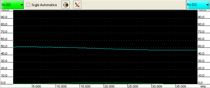
In the following picture, the best result I’ve been able to achieve with my setup:
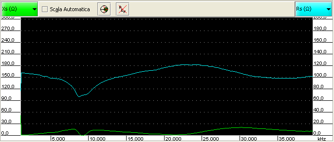
Sure it is not perfect, but it looks good.
The resistance line (cyan) reports values around 100Ω.
Let’s read with the multimeter the exact value of the load:
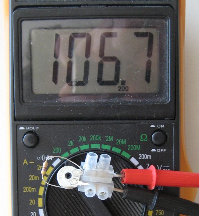
It confirms the readings! Note that I’m using a tiny 2.2K trimmer with a 470Ω resistor in parallel: I don’t have a lot of resolution so I consider these reading accurate enough for my setup.
Using the math formulas
The formula to calculate the characteristic impedance Z0 of a transmission line is well known.
It usually requires the relative permettivity of insulator between the conductors, but this value can be calculated using the velocity factor.
Fortunately, our miniVNA is able to calculate the velocity factor of any line with a pretty good precision, so here it is the formula that uses the velocity factor:
Z0 = 276 * Vf * log10 (d/r)
Where:
- Vf is the velocity factor
- d is the distance between the center of the conductors
- r is the radius of each conductor
Note that d and r must be expressed in the same unit, no matter which one: mm, inch or whatever you like as far as they are measured with the same unit.
My wire had the following characteristics:
- Vf = 0.73 (measured directly by miniVNA)
- d = 4 mm
- r = 1.25 mm
The resulting Z0 value is 101.7Ω, which matches quite accurately what I have measured.
Time-domain measurement
[Updated on Aug. 21th, 2016] – I later on sold my miniVNA a invested into a great VNWA3. This equipment can perform time-domain measurement, thus read the characteristic impedance at every point in a transmission line. This the result on a piece of the same wire:
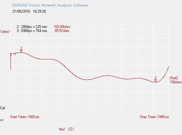
The impedance is a bit variable because my cable had bends and did some curve. However its impedance varied from 99.6 to 102.9Ω, with an average impedance of 100.86Ω. This value mathces the calculated one (101.7Ω) with a less than 1% error.
Try on coax cable
Just to have a confirmation, let’s try the same test with a length of RG-58.
This is when it is not correctly terminated (in this case load was a 680 Ω resistor):
While this is the case of a 50Ω terminator at the end of the RG-58 cable:
By the way, the miniVNA measured a cable velocity factor of 0.73 for the stereo line (that has heavy insulation) and 0.65 for RG-58 (which is pretty accurate, since the “formal” value is 0.66).
73 de IZ2UUF

That is great thinking. Your results look very good.
Some things can be pretty simple.
And you just proved it, I would never have thought of this but will keep it in mind..
Garry W8GMF
Thanks Garry!
vy 73 de Davide IZ2UUF
Great idea. I will try it out today. Question: for the test to be most accurate, would it not be best to have an RF choke between the parallel line and the VNA to avoid any skewing on the coax shield caused by the balanced to unbalanced combination?
Hello Ray.
Proper testing should be made at the end of a balun with the calibration plane brought at that point. This is something easy to do with a SOL (Short Open Load) calibrated instrument; I don’t know how reliable would be with a Load-only calibrated instrument like the miniVNA.
However in this the common mode path doesn’t seem to be very relevant: my plot wasn’t flat and this was symptom of unwanted reactances which I did not investigate (Common mode? Trimmer reactance?), but interpolating the overall curve I still had a good feedback on what the line characteristic impedance was.
This discussion is stimulating my interest: at the time of this article I didn’t have the equipment I have now, like the VNWA3 and other instruments. I think I’ll redo the measurements including a balun SOL calibrated at its end.
Vy 73 de Davide IZ2UUF