
In the world of HAM radio, there are several myths that survive through generations despite them clashing with laws of physics. However it is quite interesting to see how easy is to debunk some of them with very simple experiments.
The radiating line myth
In HAM radio discussions “experts” frequently advise against antennae tuned by a tuner for a list of “technical” reasons. Often, one of them is that due to increased VSWR, the line begins to radiate, causing any kind of interference.
Let’s try!
Smartest myths are usually founded on unverifiable facts: people are left to choose whether to believe or not. This one, instead, is very easy to verify with a simple experiment.
Let’s start measuring the field radiated by a true antenna:
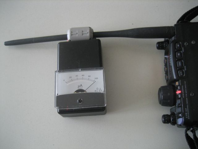
As we see, as soon as the FT817 goes on-air (red light is on), the RF current meter detects immediately a very strong field radiated from the antenna..
Now, let’s repeat the same experiment on a coaxial cable terminated by a 50Ω resistor:
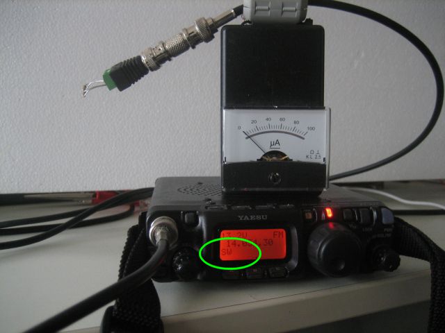
As expected by everyone, the dummy load is perfectly matched, there are no standing waves and the coaxial cable does not radiate. The VSWR meter, in the green circle, reports “1” (no bars) and the little resistor becomes immediately scorching hot.
It is now time to test the myth. We repeat the same test above but, instead of using a 50Ω resistor, we use a different mismatched value (150Ω) that causes standing waves on the coaxial cable but without triggering the transmitter protection. It the myth is true, the standing waves should cause the coaxial cable to radiate. Let’s try:
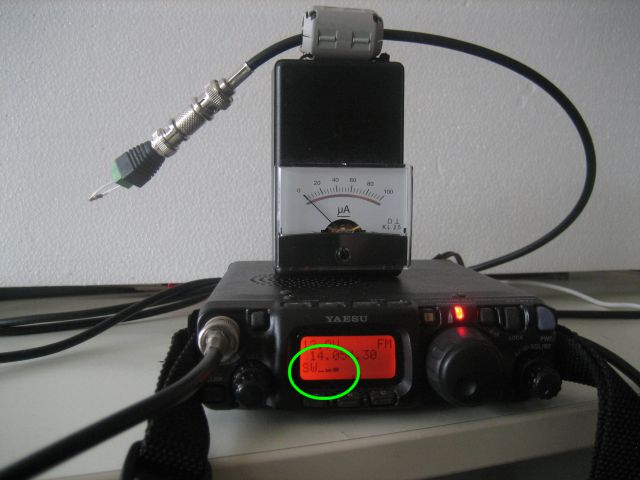
As we can see, the VSWR meter shows some bars due to reflected power. The little resistor becomes immediately red-hot, but despite of the experts claims, no radiation whatsoever is detected from the transmission line. Wasn’t VSWR expected to cause the line to radiate?
The explanation
The reason why the coaxial cable does not radiate even on high VSWR is very simple and it is explained by Maxwell laws. They say that a variable current running along a conductor causes a radiating E/M field to be generated. The transmission lines, like the coaxial cable, have the task of transporting energy, not radiating it. So, how do they work?
To avoid radiation, transmission lines employ two conductors that carry equal but opposite currents. These currents do generate an E/M field each, but being one the opposite of the other, they are mutually cancelled.
We can easily verify this statement by modifying a coaxial cable so braid and center core run separated for a few centimeters:
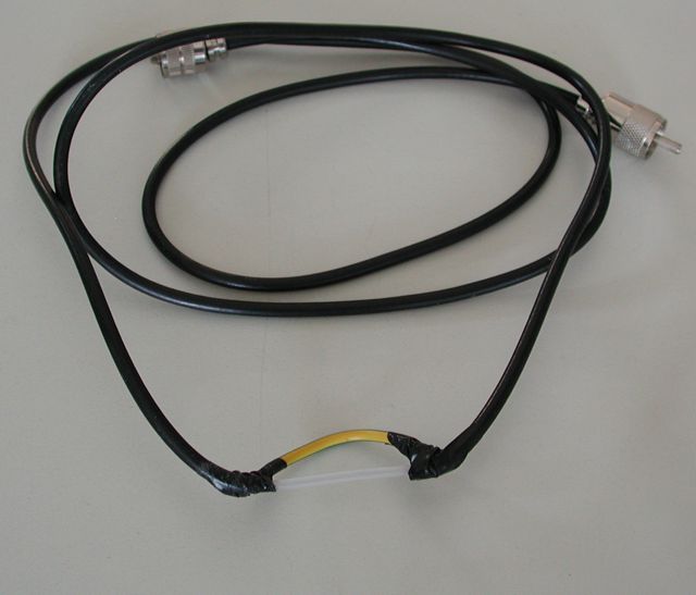
We can now measure the current running on each wire when terminated on a dummy load:
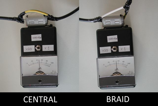
As we can see, each wire, if taken separately, does radiate. Also, we see that each wire radiates the same amount power of the other.
With a two channel scope, this is even more evident:
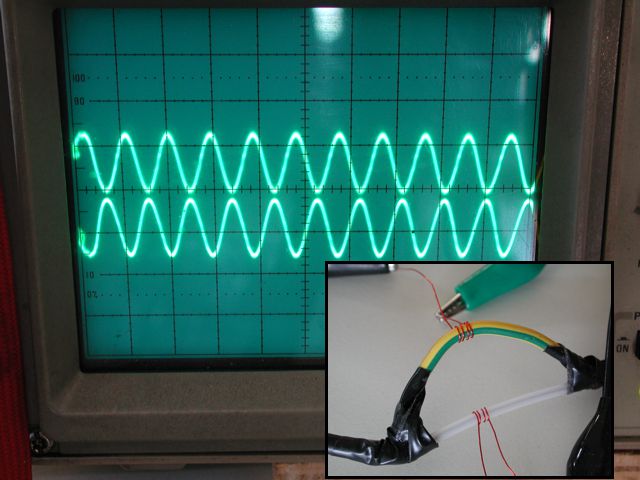
With the scope we can see the two currents of same amplitude and opposite phase.
When the load is not matched, as it happens for our 150Ω resistor, the power can not be transfered completely to the load and it is reflected. This causes the appearance of standing waves on the transmission line: within the line, we will find spots carrying an higher current and other with an higher voltage. However, the standing waves are generated on both conductors: they are symmetrical, with identical amplitude and opposite phase so, once again, they cancel each other.
For this reason, we might experiment line radiation and increased VSWR together, but high VSWR itself can not be the cause of line radiation.
So, when does coax radiate?
In order to cause the coax to radiate, the currents must be unbalanced. This means that the current running on the braid and the center are not equal and opposite anymore. Their sum is not zero and the resulting current (called common mode current) radiates. Note that this can happen also when the system is perfectly matched (i.e. with VSWR=1).
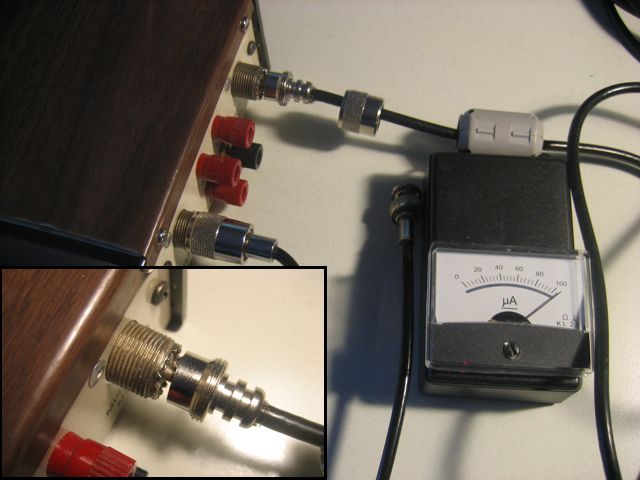
We can see this phenomenon by feeding a single conductor, like the central wire. In this case, there is no opposite current on the braid to cancel it and this forces the coaxial cable, despite of its shielding, to become a wonderful antenna:
Conclusions
There are several reasons that can cause coax line radiation; most of them are related to wrong or missing use of a balun, but none can be imputed to load mismatch. It can happen that a common cause provokes both high VSWR and line radiation, but VSWR can be taken as symptom, not the cause.

Brilliant explanation from a great OM. Thanks.
Thank you for that thorough explanation Sir.73
In a nutshell.
If I1 and I2 aren’t equal or there is serious mismatch at the antenna, there is a “common mode current” running on the outside of the coaxial cable, and there will be radiation!
Harmful in most of the cases. (RF bites, distorted voice, key clatters etc)
If “I1 and I2 aren’t equal” you have unbalance, the fields don’t cancel and you do have line radiation (common mode radiation).
If you have “serious mismatch”, you have standing waves on both conductors, they cancel and they do not radiate.
If I1=I2 (i.e. identical in amplitude and phase), why should be the standing wave ascribed to “I1” be different from the one ascribed to “I2”?
In other words, your sentence “If I1 and I2 aren’t equal or there is serious mismatch at the antenna” should be rephrased as “If I1 and I2 aren’t equal and not if there is serious mismatch at the antenna“.
In a nutshell, the “or” conjunction is exactly what the myth is about.
Obviously, mismatch and unbalance can coexist, but they are not related. This is what this article is about.
Vy 73 de Davide IZ2UUF
Thank you likewise from here for a straight, simple explanation, and blowing the myths away!
…de John, G0VPJ
Very nice and simply put explanation Thanks 73 Konrad KC9NUW
well done!
Excellent article thank you
The measurement suggests wrong results. Coax radiation has several ingredients. One is common mode. The other one is caused by the attenuation of the shield. The shield IS NOT TIGHT. It leaks. And it leaks more when VSWR is higher because voltages and currents are much higher every quarter wavelength. THERE it leaks more upon high SWR. The measurement method is simply not sensitive enough to show the additional radiation. Use a vector network analyser and a parallel cable for pick-up. You will see. If not, attend my lectures. It is one of my demonstrations.
Hello Fritz.
Obviously you are right. Load mismatch causes greater current within the line, which provokes higher Joule attenuation due to resistance and, of course, a greater radiation due to leakage.
However, as happens in engineering, the problem is not understanding whether an event occurs, but its relevance according to the application being considered: the word “zero” is a synonym of “negligible”.
Let’s take the example above: a 150 ohm resistive load (VSWR=3) implies an increased leakage ranging somewhere from <1dB to 2dB according to cable length. An average cable leakage is between -70dB and -100dB (see http://www.w8ji.com/coaxial_cable_leakage.htm or http://www.arrl.org/files/file/Technology/tis/info/pdf/8104028.pdf). Adding 2dB to this leakage can be considered negligible. Even with a 500 ohm load (VSWR=10) leakage is increased by only 6dB. And whatever the leakage is, adding a few dB to it, in normal HAM radio operations it will not change its nature: if leakage represents a real problem, it does so with or without few additional dB’s.
Instead, even a little unbalance causes a huge increase of common mode radiation. If I attach a short wire to the center conductor of my dummy load, the RF ammeter on the coax goes to full scale: I have to select the x10 scale and use minimum power (0.5W) to have readings that are not permanently somewhere over the top. I recorded the experiment above in the video below: the field generated by unbalance was so strong that not only the RF ammeter went full scale, but I’ve been able to call CQ and be copied by a CW reverse beacon:
http://www.youtube.com/watch?v=UHVGLbGOKZs
The difference between radiation due to unbalance and increased leakage is not comparable and so they are their effects on real world HAM radio applications.
The simplicity of my RF ammeter represents the needs of HAM radio application: if the needle doesn’t move (or even it moves a little) when feeding the line with 100W, whatever radiation it is, it can be considered negligible: because resulting pattern distortion is negligible, resulting RF in the shack is negligible and resulting common-mode noise is negligible.
In my opinion, comments like your, coming from a very authoritative person like you, are very precise under a scientific point of view, but without underlining the real figures, simply help spreading the myth. If a friend of yours is coming to you asking for help because with its SWR=3 end-fed antenna is receiving electric shocks from his microphone, would you advise him to better tune his antenna to solve the problem, as we read on many HAM radio forums? This is what this post is about.
vy 73 de Davide IZ2UUF
Thank you for the excellent article. Very well thought out.
Hello Anthony.
Thank you for your appreciation!
By the way, I see you are from Parma (OH): I graduated in 1988-1989 at the Berea High School, I guess you know what I’m talking about! 🙂
Vy 73, Davide IZ2UUF
Brilliant way to explain it. It looks like you used a 1/4 watt 50 ohm resister and I am surprised it did not turn black, smoke and fail in seconds, even on low power.
Hello Tim.
I used 0.25W resistors with the TX power set to its minimum, which is 0.5W.
To make a measurement or take a picture you need just one second TX or so. The resistor doesn’t have even the time to become warm.
If you look at attenuators datasheets, they are rated for a given average power and a much higher low duty cicle power. For example, my Weinschel 3200 attenuator is rated for 1W average, but it can handle up to 50W with 1uS pulses and duty cycle of 1%.
Vy 73 de Davide IZ2UUF
I think this is a great article showing the truth, but I am more interested. In your test meter and how to build one. All the best and 73’s. Don. VA3DDW
Using current and magnetic field cacellation is good way to explain,but what if opposite voltage on the center and shield emitted slice different electric field,as shield may not be perfect.
What is the device you are using Treasure the radiatipn?
I am not so sure about your demonstration. A 3:1 mismatched load on a 10 ft piece of RG-8x will have a feedline loss of .09 dB. If the input power is 0.5 watts then the amount of loss in the 10 ft cable will be about 10 mW. If the loss were radiation then it would likely be distributed along the entire 10 feet. If the loss is heating then it will be focused on the high current points in the line.
But let’s assume it was radiation….. Your current sensor is perhaps 1 inch long. To sense radiation it would only be exposed to 1/120th of the 10 mW being radiated or about 80 microwatts. What kind of meter deflection would you expect with 80 microwatts?
I think your conclusion is absolutely correct and the 10 mW of line loss in this case is converted to heat concentrated at the high current points in the line. But I don’t think your demo proves the point.
….. and now I am not even sure the conclusion is correct.
I just did a test myself where I wrapped a length of hookup wire spirally around a 6 foot length of RG-174 and then connected the hookup wire to the input of a spectrum analyzer. The RG-174 was connected to a signal generator supplying 14.1 MHz at +10 dBm. The other end of the RG-174 terminates in a switch box that allows me to switch between 50 and 150 ohm terminations. On the spectrum analyzer I took power average samples, 100 samples each, of the signal picked up by the hookup wire. The 150 ohm terminated wire consistently produces signals 0.7 to 1.1 dB higher in multiple iterations than does the 50 ohm terminated wire.
This would indicate to me there is indeed radiation from the coax and it is VSWR dependent. What do you think?
Hello Warren.
You are picking up the increased leakage due to increased current. This topic has been pointed out already at this comment: http://www.iz2uuf.net/wp/index.php/2016/01/30/the-myth-of-swr-causing-coax-radiation/#comment-400
The higher the mismatch, the higher the current in the cable, the higher is radiation due to leakage.
The goal of this article is to demistify the myth that the phenomenon of significant coax radiation (i.e. the one that causes relevant effects, like RF in the shack or common mode noise pickup) can be due to mismatch. It is not 1dB of extra radiation above the normal leakage that all people always have according to the quality of their cables that can make the difference of having RF in the shack or not.
The instrument I used is sensible enough to pick up far less than the amount of radiation needed to create any relevant effect in normal ham radio operations.
Add a little unbalance (like a piece of extra wire connected to the center conductor in parallel to the dummy load) and you will see the coax radiation become huge.
In the following video I transmitted with my 817 QRP RTX in a coax terminated with a load. The instrument shows no relevant radiation from the coax. As soon as I attach a short wire to the dummy load side connected to the center conductor, the coax starts radiating making the instrument jump to full scale. Radiation of the short wire and the coax was so strong that I have been copied by a reverse beacon in Germany!
https://www.youtube.com/watch?v=UHVGLbGOKZs
This is the level of radiation normally attributed to high VSWR, which is instead due to line unbalance, that this article is talking about.
The message is: “Are you experiencing RF in the shack? Don’t try to solve it by better tuning your antenna, because it can’t be that”.
Vy73 de IZ2UUF
The transformer used to sample the RF current is sampling ALL of the current that pass through it. This means that the current flowing on the inside of the coax (due to the differential-mode), and the current flowing on the outside of the coax (due to the common-mode, and possible courtesy of skin effect) are being summed. This will also be the case where you split the inner and outer.
Because the shield doesn’t form a complete circuit in the transformer, it can’t shield the coax inner current from being sampled either (check-out how VSWR meters are made). This means that the first measurement is measuring the sum of the coax inner current, the shield inner current, and the shield outer current.
The line may well not be radiating, but you haven’t proved that.
73 Andy, G4KNO.
Great explanation.
You are putting a 59ohm resistive load only.. with a mismatch you are forgetting about capacitve and inductive reactance which you haven’t implemented with your experiment. With iether your standing wave can go out of phase giving radiating outer coax.
A dummy load has no capacitance or inductance. Your experiment is void.
Hello Pete.
Every now and then pops out some “expert” saying that if the load is reactive, the “standing waves would go out of phase and radiate” or something like that.
Why current and voltage going out of phase among themselves (this is what the reactive load does) would make the current on inner conductor go out of phase with the current on the outer conductor? It’s the currents being symmetric and opposite on two parallel conductors that cancels the field and block radiation, not current and voltage being in phase.
By the way, in this video that I filmed last year, https://www.youtube.com/watch?v=rDLsoI14hH0 – remember to enable the subtitles in English – at 4m58s there is the same experiment repeated on a reactive load.