
In my experience with computer antenna simulators (I mostly use 4NEC2), I had the feeling that those tools, if correctly employed, can be quite accurate. Unfortunately, when working on shortwave antennas, the interactions with the surrounding environment make the results a bit approximate: such long wavelengths make impossible, at least for us hobbyists, to avoid the environment to fall into the antenna near-field, changing the expected antenna behavior.
Today I wanted to make a simple experiment to answer a curiosity I had since long: how accurate can be a computer simulation when an antenna can be realized without stray environmental and construction interactions?
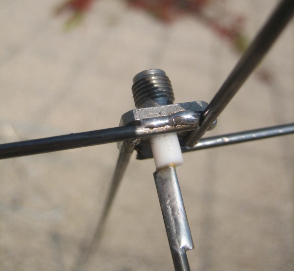
For this purpose, I created a simple 300 MHz ground plane antenna trying to reduce its parts to simple and linear components that could be easily simulated.
Using a SMA panel connector, I soldered four 24-cm long, 2mm diameter, radials to the flange and another 24-cm long radiator to the center pin. The center pin plus the radiator was exactly 25 cm long. I kept the radials flat and perpendicular to the vertical radiator to simplify the computer simulation and avoid adding other errors.
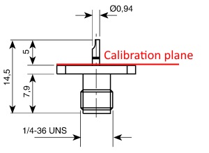
I have then taken a SMA terminated cable and SOL calibrated my VNA (VNWA3) so the calibration plane was right on the SMA flange:
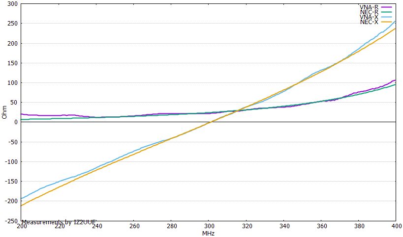
I placed the antenna on a pole, several wavelengths clear of any other object, and run a VNA scan from 200 to 400 MHz.
Results
The resonance point calculated by 4NEC2 was at 298.745MHz, while the measured one was at 301.049MHz, i.e. a very tiny 0.77% difference among the two. On 4NEC2 I tried both free-space and raised 3m from real ground without any significant difference: being an antenna for the 1m band (300MHz), 3m of distance is more than enough to cancel the effects of ground on the impedance.
This is the direct comparison of the R and X values as calculated by 4NEC2 and measured by VNWA3 in the 200-400MHz range. The simulated and measured curves are almost identical:
The following graph evidences the percentage of discrepancy between the measured and the calculated value of the impedance modulus |Z|:
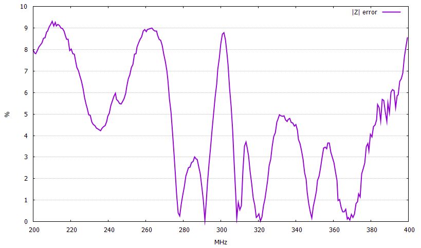
The maximum discrepancy is around 9%, which seems pretty accurate for this kind of applications.
Conclusions
If systematic care is taken to reduce the undetermined relationships between the antenna being developed and the surrounding environment and the structure design is kept within the documented technical limits of the instrument, a NEC simulation can be very accurate.

Leave a Reply