
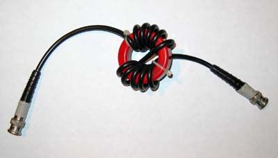
I happened to stumble across some antenna projects showing common mode chokes 1:1 baluns made of some turns of coax wound on T200-2 iron powder toroids.
Will they work?
The role of a choke
A choke BALUN works by letting through the differential current and by hindering the common mode one by opposing some impedance. The key value showing chokes merit is the CMRR, or Common Mode Rejection Ratio. This value is the ratio of common mode gain over differential mode gain. In other words, CMRR is the attenuation of common mode currents in dB minus the insertion loss in dB. The latest is usually negligible in this kind of BALUNs on short waves.An article by Ron W6WO appeared on QEX 11/12-2010 estimates that CMRR should be at least -20dB on the whole range of interest, -30dB on narrow band BALUNs.
Iron powder vs. ferrite
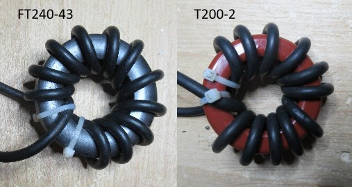
In order to evaluate the choking characteristics of the “red” toroids, I prepared two chokes by winding 12 coils of RG-58 on a iron powder T200-2 toroid and a ferrite FT240-43 one.
Using a vectorial network analyzer, I measured the CMRR on both chokes obtaining the following results:
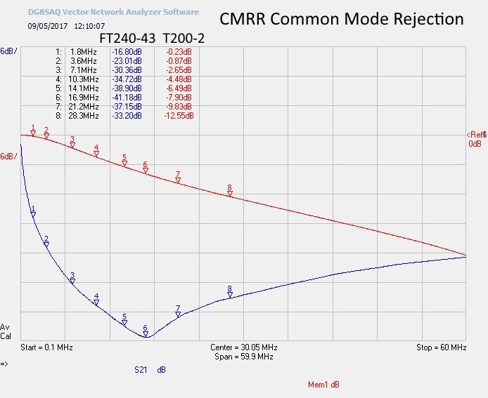
As we can see, the CMRR of the T200-2 is well below the -20dB lower limit set by W6WO, becoming negligible in most bands. On the other side, the CMRR of the choke on the FT240-43 ferrite is very good on a wide range of frequencies.
Our valuable friend Steve G3TXQ, to whom I send my sincere wish for a speedy recovery, published on his website a famous analysis of several types of chokes. He determined the quality of a choke BALUN by considering its common mode impedance |Z|. Values below 500Ω are not considered “choking” at all, values between 500Ω and 1000Ω are marked in red as “very poor”, while the “green area” starts at 4000Ω.
We can now evaluate the two contenders using the |Z| criterion set by G3TXQ:
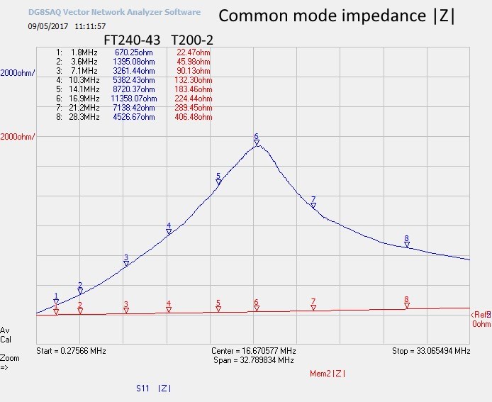
In the 1.8 to 30MHz range, the choke made of the T200-2 never goes even close to the 500Ω barrier: in G3TXQ table would not even appear (and in fact it doesn’t list any iron powder choke).
The conclusion is quite evident: don’t make short wave chokes with iron powder toroids!

I have been working with 1:1 Balun/Chokes for a while now, mainly to determine its 1st job of reducing CMC TO -20 db or better. I have wound the DG0SA designed 1:1 Balun/Choke, I measured the CMC reduction in my HP 8711A VNA and my Rigol DSA815 Spectrum Analyzer finding the results very similar. I do not have the software to determine the Choking Z however I would think that it would be quite adequate. I believe that one must first determine how well the 240-43 Toroid acts by winding 10 turns of wire and viewing how well the Toroid acts on the VNA first and also checking its Inductance. Mine measured 138 uh. The type of wire that is used is extremely important as Wolfgang has stated. His AWG 18 PTFE is slightly different then what I was able to obtain here in the states. The results though were different and my Balun/Choke exhibited a greater reduction in CMC than Wolfgang’s. Again, Toroid difference, wire differences make the big difference. So we can justifiably state that there are different flavors of these. As long as it prevents RF from coming into the shack and presents a good SWR we can safely say we have a good Balun/Choke. I am sad to report that I have purchased several so called Baluns and most have less than 7 db of CMC reduction. 73’d
Greetings!
Thank you so much for this article!
I like to make my own baluns and ununs and this really helps!
Thank you and God bless you,
Will Brokenbourgh – AF7EC
Pacific Northwest, USA
Thanks for the analysis. Loads of food for thought
73
Mike G4KUY
HI, I did notice that before I came to this page. I had 2 toroids T-240-43 large and a T-200-30 Red.
When I did hook up analyzer and on the computer as well.. I was amazed at how much lower the SWR Reading on the Toroid was for my 4:1 Balun transformer T-240-43
Hi,
how did you connected the balun to the VNA to measure the CMRR?
Did you used the BNC connectors or measured the coax braid only?
Thanks and 73s
iz5xrc
Thank you for posting the information. I find this most useful to save wasting time kidding oneself the balun was wound as well as possible. With out the correct material it would obviously be just a waste of time. 73 de John – G0WXU.
Mind showing the test setup with connections depicted? The 50 Ohm coaxial transmission line ends shown (red or blue case), when connected to a network analyzer, will always result in a flat insertion loss (S21) independent of the toroid’s presence outside the shield. This is because the EM fields exist completely within the shield (E-field like spokes outward from the center conductor, and H-field like concentric circles around the center conductor), both transverse to the direction of propagation.
Are you connecting it differently, perhaps with an independent parallel ground, treating the coax as a single “solid” conductor (ignoring or shorting the center conductor to the shield) and using an external ground reference? That wouldn’t be a classical S21 measurement for the coaxial…
If you are using a separate ground/return, how do you control the effects of this new ground reference (length, uniform/fixed distance to coaxial) and how did you physically connect it to the VNA?
Hi, in the absence of answers from elsewhere I can tell you my method which is substantially the same as that of G3TXQ. In essence the common mode choke is tested as a two terminal device. An easy test fixture is just a groundplane of unetched PCB or tin plate where the braid of each cable from the VNA terminates. You can also just attach the braids to each other. The centre of each coax can conveniently end in a crocodile clip. So this is the test fixture…
To test the common mode choke simply attach one clip to the braid at each end of the choke. (It is not necessary to connect the centre conductor for testing).
In my own tests I found a single core could readily produce 35dB of atttenuation at best. G3TXQ in his tests went to the extra trouble of separating the inductive and resistive components of the impedance. I did not…
FWIW for most of my general HF use I found that about 12 turns of coax on an FT240-43 was very successful. I used a PTFE dielectric coax for it’s high power handling and hopefully to resist the centre conductor migrating. 773 de G0FVT
…. it’s my understanding that the 31 ferrite material is even better for choke baluns…and is what Palomar Engineering sells excusably for their linear coaxial choke baluns to suppress common mode current issues and to eliminate coaxial noise suppression. They say the 43 material is the stuff to use for ferrite 49:1 or 4:1 for Delta Loop or EFHW balun transformers… it’ll work but it’s not the best stuff. I was just at a hamfest seminar put on by them… and they explained the difference. The red powdered iron cores can be used for non resonant UNUN applications if the power isn’t too high.. a good example of this are the QRP Guys who make their little portable non resonant antenna kit for POTA work.. it has a little red iron powder #2 core in it.. I think they saturate easy so 50 or 100 watts would he tops. Go on their.. website Palomar Engineering and a lot of stuff will be explained. A lot of research has gone into this subject and I don’t think your gonna reinvent the wheel. Richard
I have only one T130-6, is posible use for comune mode choke for 7mhz antena whip? YO3HGR qrz page info antena whip. Tnx, 73.
No, it does not work! It should be Material 43, better material 31… or similar from other brands… And if you don’t have it: 10 or 15 turns of coaxial in a 4″ PVC form will reasonably improve the I3 on the outside of your coaxial cable…
Interesting observations!
Question: Would a T200-2 Toroid be suitable for a 9:1 or 49:1 UNUN ?
Thanks
Steve
W8SAW
I don’t understand anything anymore… which one is better ?