
(Note: this article is available also in Russian, thanks to Oleg UA9UAX!)
[PL-259 vs. N on 430 MHz follow-up] – Many OM assert that they can not withstand the performance penalty introduced in the 430 MHz band by a SO-239/PL-259 pair.
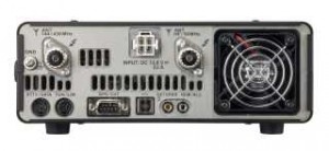
Curiously, all the major rig makers seem to ignore this fact. For example the Icom IC2820, the IC7000 and the newer IC7100, the Yaesu FT857/FT897, Alinco DR635, Yaesu FTM-400 and the new Yaesu FT991, among with many others, have a version with SO-239 on the UHF band.
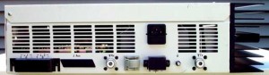
Even the Motorola Radius R100 UHF professional repeater has two SO239 on the back! We are not talking about cheap rigs: many of them are top the range.
In one of my previous posts, PL-259 vs. N on 430 MHz, I tried to verify this issue with a simple measurement. Those tests received some interesting criticism, so I did further testing: if this penalty is true, there must be a way to “see” it.
Let’s play harder
My previous post set off many comments and criticism on various social networks. Some were out of topic: I am not debating about GHz measurement instruments nor QRO EME transmissions. Some argued that the test was not realistic because no power was used; others observed that my connectors were cheap junk and this explained why the N-N connection performed as the PL259-SO239.
So I decided to make further investigations, both with measurement instruments and with my European Yaesu FT857, which is one of the rigs sold in Europe with a N connector and in the rest of the world with a SO-239.
Also, I wanted to remove my N converters from the equation: the tests will have to be done comparing a direct N->N connection with a N->PL259->SO239->N:
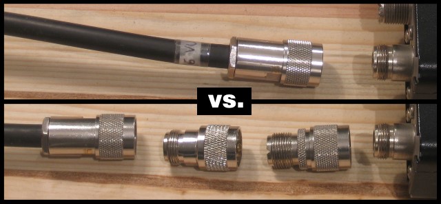
This is unfair to the PL, since is being compared to “no connector”. But whatever result it would have given, I expected not to be worse than a rig directly equipped with SO-239.
Some serious measurements
The N connector is undoubtedly an electrically better connector. Its impedance is maintained precise and constant inside the whole RF path, while this is not true for the PL connector.
The S11/S21 plot of my N->PL259->SO239->N converters reports:
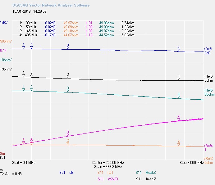
At 435 MHz, the PL causes VSWR to jump at 1.18. At the same frequency, it adds an attenuation of 0.17dB. Note that this measure (S21) includes both the attenuation due to impedance mismatch (S11, reflected power) and attenuation due to internal resistance.
We can actually see the impedance inside the PL connector by running a Time Domain Reflectometry with step response:
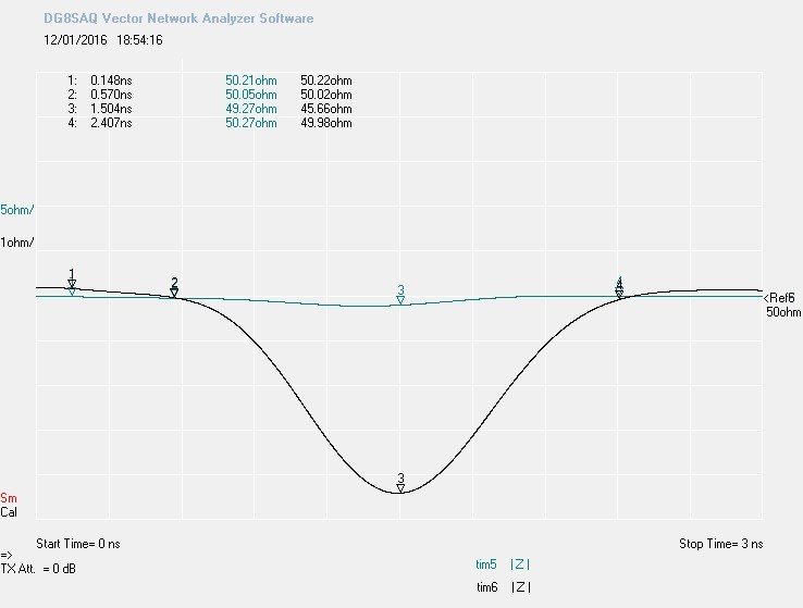
The green line shows the N connection on its own: impedance is almost perfect (50Ω) everywhere. The black shows when the SO239-PL259 pair is added to the chain: inside this PL the impedance drops to less than 46Ω. The resulting impedance transformation, that causes increased VSWR, is more significant at higher frequencies, because a few millimeters become a relevant fraction of the wavelength. This explains why by adding this PL converter, VSWR at 435MHz goes up to 1.18.
Down to real world
Now we have established that our PL converter adds some millimeters of transmission line with a characteristic impedance of 46Ω. We verified that this causes VSWR to raise to 1.18 and we measured that the transmission loss is 0.17dB.
Ok, but what do these figures mean on real-world operations? Can a human operator detect the effects of that, or are we facing some kind of audiophile syndrome?
In order to answer this question I’ll test my Yaesu FT857, one of the models that is produced both with SO239 and N. Mine has an N connector and, as anticipated, I will test it with direct N-N vs. N->PL259->SO239->N double conversion.
First of all, am I safe to run transmission tests with VSWR at 1.18? The FT857 user manual states:
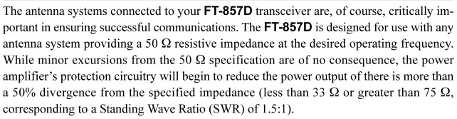
In my case, VSWR is 1.18 and impedance is |Z|=44.87Ω: I am well inside the “minor excursion” range. I should be safe and expect “no consequence”. After all, a VSWR of 1.18 implies a theoretical reflection of… 0.682%!
Reception test

Obviously I could not run reception test by tuning to a local UHF FM repeater and reading the S-Meter that bangs over 9+60 even without an antenna plugged in. Also, I did not want to tune to a weak distant station, because natural QSB would have invalidated any reading.
Instead, I put my signal generator on the roof to serve as a steady, low power, nearby CW beacon. I wanted the test signal to be weak but not affected by propagation. The signal was then received by a vertical Comet GP-6 dual band antenna on the same roof about 20m away.
To have readings more accurate than my ears and the internal S-Meter, I extracted the signal from the FT-857D IF and I fed it to an SDR receiver.
Test 1 – 10+ meters of RG58
As a preliminary test, just to see whether the “test bench” was working, I tested reception with and without the insertion of extra 10m of cheap RG-58.
As expected, the signal dropped significantly. With such a weak signal, the note from the radio loudspeaker become very noisy. A weaker signal would have disappeared in the noise floor. The difference was immediately perceivable both by watching the SDR waterfall and by listening to the radio itself.
Test 2 – Beacon, N-N vs N-PL-SO-N
In this test I added and removed the N->PL259/SO239->N converters pair.
Even with this setup, the fluctuation of the received signal was too wide (over 1dB) to appreciate any difference: the values appeared to float within the same range.
Test 3 – Signal generator, N-N vs N-PL-SO-N
In the attempt of reducing the floating, I connected the signal generator directly to the radio. Again, I tested with and without the the PL converters.
This time the dBm fluctuation was much lower, mostly within few tenth of a dB. However, neither in this case the penalty of having an extra PL259/SO239 conversion could be detected.
Transmission test
Some of the criticisms about my previous test were that it was conducted at very low power (0dBm, 1mW).
The FT857/897 can deliver 20W on the UHF band, while other rigs of those available with SO-239, can deliver up to 50W. I set my FT857 to maximum power, connected it to a Weinschel 3GHz attenuator and then into my spectrum analyzer.
When transmitting with the PL converters, the FT857 showed an increased VSWR by lighting one dot in the SWR meter:
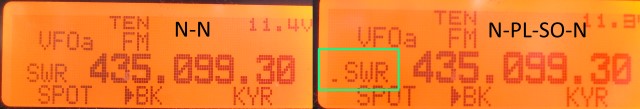
However, the readings on the spectrum analyzer were identical:
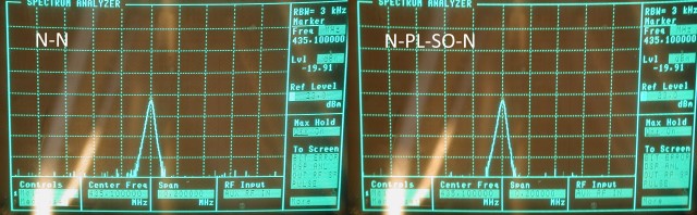
My spectrum analyzer, despite of the two decimal digits on the display, has an actual resolution of 0.3dB. Therefore, the two reported values might be different, but no more than 0.3dB, which is coherent with the 0.17dB measured by the network analyzer. Taking in account the attenuation of cables and attenuator, this measurement reported that my FT857 was actually delivering over 25W.
Bolometer test
I measured the output power of my FT857 in UHF (433.150 MHz) set to maximum power (20W). I used a HP 438A bolometer with a 8482A power sensor through a 30dB attenuator.
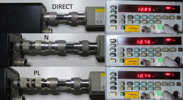
The power measured directly at the output connector was 42.85dBm (19.3W). Then I added a N male-male converter connected to a N female-female converter: the power lowered to 42.76dBm, i.e. 0.09dB less than the direct connection. This means that adding two N converters costed 0.045dB each.
Finally, I did the same but using a N->SO239 and a PL239->N converter in series. In this case, the output power went down to 42.74dBm, i.e. 0.02dB less than the N-N pair of connectors, and -0.11dB versus the direct connection.
The use of a SO239-PL259 pair of converters in the 433 MHz band instead of a N-N pair costed only 0.02dB.
Final considerations
My goal was to understand whether a UHF radio delivered with a SO-239 instead of a N plug carries a price in terms of performances. In my investigation, I have not been able to find a single test involving the real rig, even if connected to measurement instruments, that could show any difference: only a Vector Network Analyzer, with an accurate setup and calibration, has been able to characterize the SO239/PL259 connection.
Furthermore, I have tested a plain “N-N” connection versus a “N->SO239->PL259->N” pair: a PL-equipped rig would use a somewhat better “SO239->PL259” direct connection.
Under the light of these facts I have to conclude that, in the 70cm band there is no relevant performance difference if a N, SO239 or even a PL/N converter is used in this kind of rigs.

Thanks for this wonderful article. This clears many doubts and serves as a benchmark for many hams across the globe. Greetings from India, 73s de VU3TTL
I was told that real reason for N connectors in commercial radios (Police, fire etc) were because its the only water proof connector. The PL-259 (could) let moisture in the coax and of course that ruins it. Is it that important? Probably not but when you pay $4000.00 for a radio build into a block of milled aluminum with gaskets on all the covers and such I guess its expected.
PL-259 are used almost exclusively in all VHF marine radios. If they do not care about waterproofing why should us?
Amazing article, this scientific method will enlighten all hams on DU’s/4F’s stations in the Philippines. 73 de 4F1KJA
Excellent work. I’ve never concerned myself with the selection between these two connector types for 70 cm band use. You have reaffirmed my belief that the coax and termination (antenna) are the real areas of concern.
David de AE5DS, GROL, GMDSS-DO/DM
Makes sense. My audiophile friend with a tube amp, swears by his $100 solid copper, 12ga 120V line cord as improving the sound his amp is capable of putting out by not using a cheap 18 gauge line cord….forgetting they both plug into, and run through at least 50′ of cheap romex in the wall to a cheap circuit breaker in the box. The last 4′ isnt going to make a hoot of a difference. Thanks for the good write up. Ill continue to solder my PL259s on, and spend the money saved on better coax that will make a difference.
Your audiophile friend has been drinking tainted KoolAid. That brand of drink has been used by P.T. Barnum & his disciples for decades/centuries; one of the many tools used to separate weak minds from their money.
Thank you IZ2UUF!
That tends indeed to exemplify my former comment on some economics /marketing aspects of matter like these – without denying that standardisations are by all means nevessary in industry . Simply they can go against cost and competition. Hence your purpose. Thanks!
73s.
Fantastic and well documented article. Unless any connector isn’t of a low and questionable quality (i.e.’Chinese’ type), then I agree that the issue in power losses are elsewhere on any transceiver. The coaxial cable losses and the proper match of the coaxial with an antenna is what matters really.
Thanks davide for the very good read.
I agree with you on everything you wrote. The only exception would be in case of activity with UHF antenna poynting to a cryogenic source, namely EME or satellite weak signal reception. In that case, 0.17 dB additional attenuation in front of a LNA could degrade the noise figure (or better the noise temperature) of the whole reception system and this in turn would degrade the S/N.
The effect of weak attenuation in front of a LNA on the final S/N is very different in case of antenna pointing to the warm ground as in case of terrestrial activity compared to the case of the antenna pointed to the cold (and quiet) sky in case of EME. Especially at UHF.
Ciao,
Francesco IZ2DQB.
Hi, I’m just an M6 in the UK but this technical demonstration was so easy to understand. Thank you.
Interesting test
Our common usage ham frequencies are low enough for losses to be very small. Things change from 23cm and up, which like feedline losses stands to reason.
You will notice the loss and impedance bump at QRO levels,with multiple antennas and power amps and matching splitters etc, But at 20-50w No it won’t be enough of a loss to notice, At 400w on 70cm a PL259 will cause a issue, Try running your tests at QRO levels and you will see a issue.
M5IJH
“The use of a SO239-PL259 pair of converters in the 433 MHz band instead of a N-N pair costed only 0.02dB.”
The relationship is linear: 0.02dB of loss measured at 50W will translate to about a quarter of a watt (combined dissipated and reflected). At 500W, this would be roughly 2.5W. Keep going all the way to QRO (in the USA) of 1.5kW and you’ll see that it’s < 10W. You can calculate the power reflected toward the generator (your rig) and the rest makes the PL-259 a few degrees warmer.
N0ZGO
Very interesting. For my ic2739 50W fm only rig no problem about PL connector. But, as somebody stated, for high demanding work every bit counts.
So, for fm no problem. For weak signal work I will use N connectors even on 2m band.