Introduction
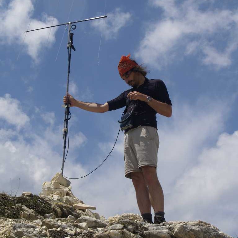
One of my favourite hobbies is to trek and climb the Alps and do ham activity wherever I reach.
During the warmer seasons, I often reach high summits: what better place for some VHF activity?
So far I worked with a 4-elements 1m long Yagi-Uda that I designed and built myself with plastic and aluminum tubings.
This antenna did work, although it got some problems.
Initially all the elements were in a single piece and, once packed, the whole assembly was about 1.3m long: when tied to the backpack, it kept on tangling to the lower branches.
So I cut in half and threaded all the elements: now it was shorter, but it took an annoyingly long time to be reassembled and it required a clean area where to work.
Last but not least, it was heavy: over 600g.
The 100g antenna
The new antenna is extremely simple, easy to build and cheap.
The boom is the second thinnest element of a 7m fishing rod that I had spare from another antenna. This element is about 1.05m long; it diameter goes from 8 to 15mm and it is not critical at all.
Elements are aluminum TIG soldering rods: 2.3mm of diameter, almost 1m long, these objects are light, thin and flexible. A bought a 1 kg box for a few Euros and it contains about 80-90 of them.
Project
I designed this 4 element Yagi-Uda using the <href=”http://www.qsl.net/4nec2/”>4NEC2. I love this tool because if correctly used, it is so accurate that I can cut directly the parts at the exactly calculated length and they will do work immediately as expected, without any further tuning.
I wanted 50 ohm at the feed point and a boom length that would fit within 1m.
The figures I came up with were:
| Element | Lenght (mm) | Position (mm) |
|---|---|---|
| Reflector | 1010 | 0 |
| Driven | 995 | 460 |
| Director 1 | 900 | 660 |
| Director 2 | 840 | 990 |
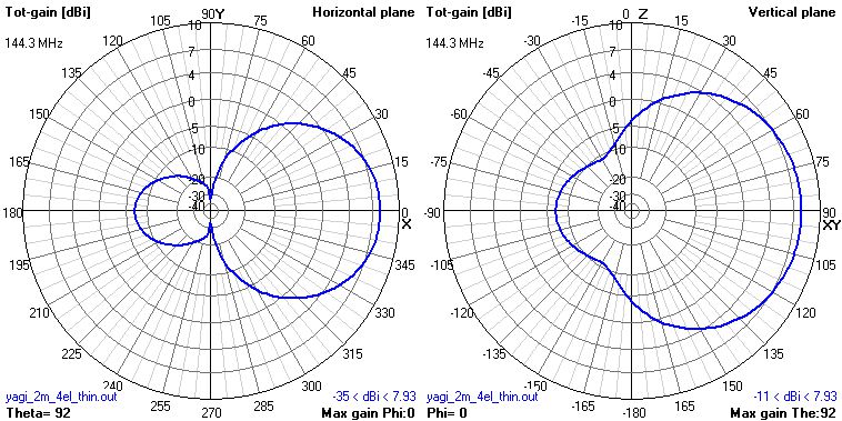
Radiation pattern
Here it is the radiation pattern in free-space:
The boom
As described before, the boom is a 1m long fishing rod segment. The elements are mounted in four pass-through holes drilled across the boom itself.
Well, drilling eight holes, aligned on the same axis lines on a conical object (as a fishing rod is) is not that simple.
Here it this the procedure I followed.
First, put the rod flat on a table and mark, on both edges, where it is touching the plane below. This gives two points that are aligned along the rod side.
Then, using a piece of paper tape, find and mark the corresponding line on the other side of the rod (see picture below):
- start with the mark done before (a)
- put a piece of paper tape and write “A” near it (b)
- put the tape all the way around and mark again the same spot, this time with “B” (c)
- peel off the tape and mark a “C” point halfway between marks “A” and “B” (d)
- put the tape back in place, aligning “A” and “B” with the first mark: mark “C” is the position of the line on the exact opposite side of the rod (e)
- do it on both edges of the rod

Using a thin string pulled along the rod and aligned with the marks, pin the position of the holes on one side. Then repeat on the other side of the rod.
IMPORTANT: do not drill both holes at once: being the rod conical, the hole below will be off center! Drill first the holes on one side, then the holes on the other side of the rod!
The radiator
The main problem with the radiator is how to make a safe and strong connection between the aluminum rods and the copper RG-174 coax: as we know, aluminum is not very tin-friendly.
Instead, I experimented a crimping technique that proved very easy and effective.
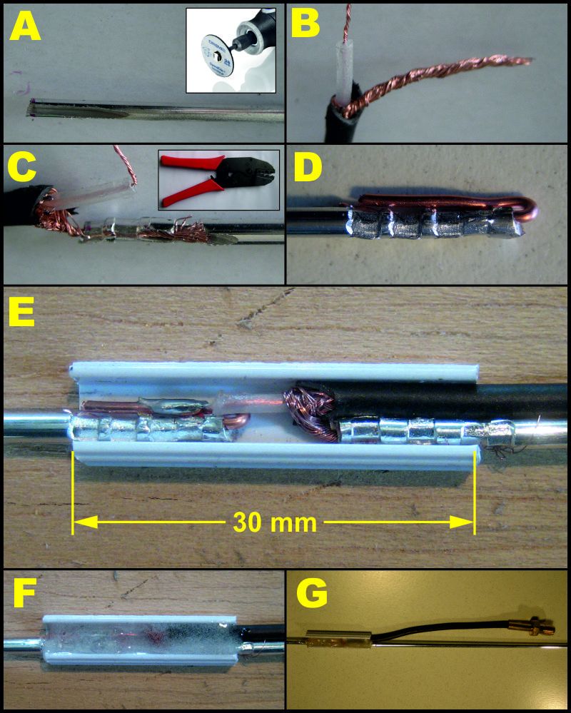
- prepare the radiator by cutting to identical rods, both half the radiator length;
- put each rod in a bench vise; with a Dremel blade, dig a “channel” in the rod; its section will then be “U” shaped (A);
- prepare your RG-174 wire as in picture (B);
- put the braid in the small channel and crimp it using the crimping tool (C);
- the RG-174 center is too weak to substain such crimping without breaking; so instead crimp a small segment of 1mm copper wire and fold it back as in picture (D);
- find something that can hold all that parts together; I used a PVC profile, “U” shaped, 4×8 mm, 3 cm long; solder the RG-174 center to the copper wire and put everything in place. With a pencil, I drawed a line on a flat surface and temporarily taped the rods in place to keep them flat and aligned (E).
- fill with epoxy glue the entire assembly and let it dry hard (F);
- complete your cable with a female SMA plug after a very shor lead (few centimeters) (G);
The parasitic elements
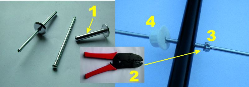
The parasitic elements (a reflector and two directors) are very simple: just cut your rods to the right lengts.
I wanted to add a blocker to each element that stopped the bar at the right position once inserted in the boom.
I cut a small slice of the external cylinder of a rivet of the right size (1). Then using a crimping tool (2) I crimped the slice on the element (3); maybe it can be done with pliers as well.
On the other side (4) I used some small caps used to close unused holes in furnitures; with a cutter I cut a cross-shaped hole an they work perfectly to hold the element in place on the other side.
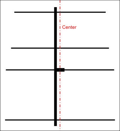
IMPORTANT NOTE – The antenna center is not along the boom: being it non-conductive, it can stay off-center; rember to fit the blockers at the right positions considering that.
Mounting and cabling
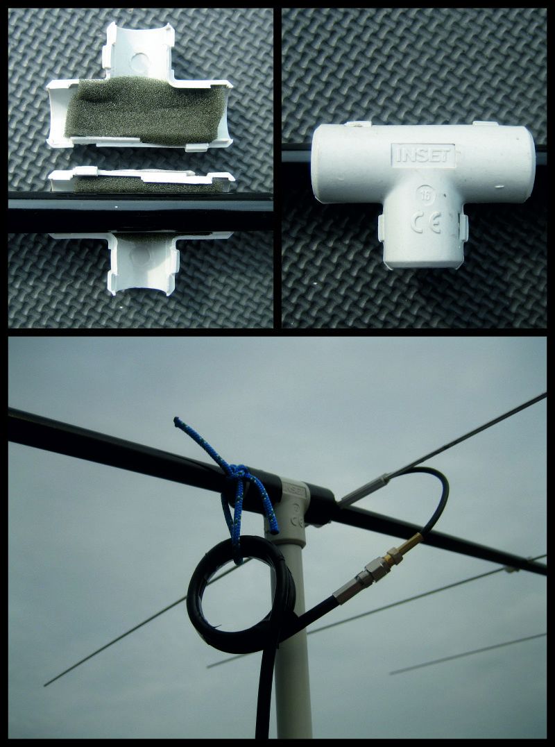
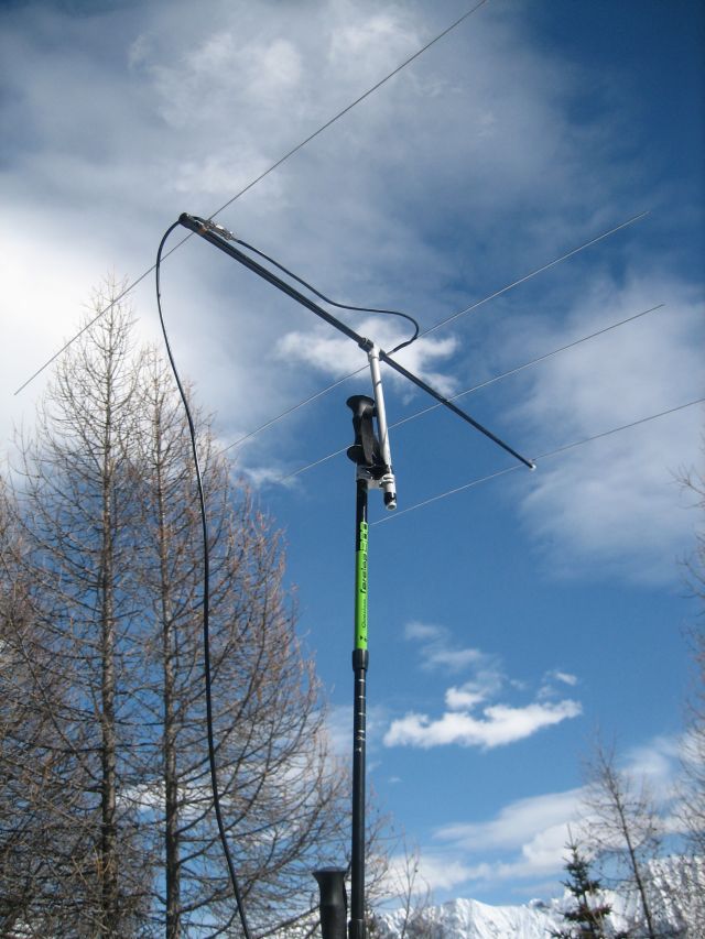
I used a small PVC T-shaped fitting for electrical conduit filled with foam rubber; this gives a nice grip on the fiberglass rod and allows rotation to change polarization.
A small choke (3 turns over 33 cm of RG-58) completes the feedline. Note that the choke is on the external feedline: in this way the antenna parts can fit inside the boom when not used.
Once dismantled, the antenna fits completely inside the fiberglass boom.

VNA measurement
The data below has been measured with DG8SAQ’s VNWA3 vector analyzer, SOL calibrated at feedpoint.
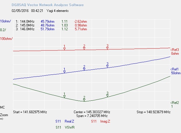
This antenna is perfectly usable on all the 144-146 range and more, with VSWR ranging from a minimum of 1.03 at 145.0 MHz to a maximum of 1.12.
Conclusions
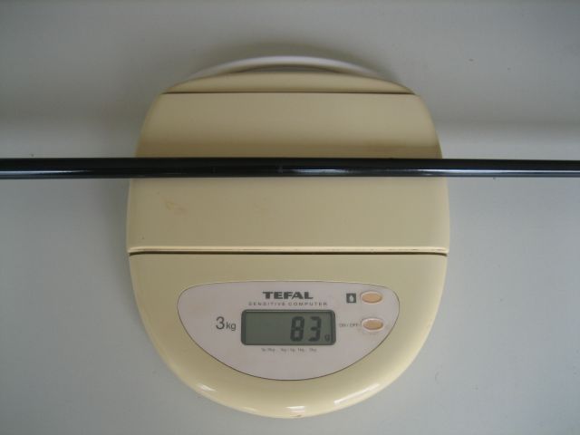
This antenna proved extremely cheap, light (83 g), robust and easy to build. It is very easy to assemble and dismantle even in hard climatic conditions.
This is the complete antenna (elements are inside) on the scale:
Actually, the fiberglass mast and ultra-thin elements combination is so effective, that I built a 144 MHz 10 elements long-boom Yagi (5 meters long) for fixed use that is permanently installed at my QTH, still in perfect conditions despite of wind and snow.
It is so thin and light that everything will do as a mast: I normally use my trekking poles stacked one ontop of the other (with Velcro straps), so I reuse weight I am already carrying.
Links
Matt KØMOS built one its portable antennae following this project and tested it at the Colorado 14er Event. Here it is his report.


Bravo Davide, grazie per il tuo suggerimento su arifidenza. 73. Andrea IW6MME
Ciao, questo design e’ eccezionale, stavo per realizzare qualcosa di simile quando ho trovato il tuo articolo su Internet. Le bacchette TIG che ho a disposizione sono piu’ corte del necessario per implemetare il riflettore ed anche l’elemento radiante… tu come hai fatto?
Ciao Alessio.
Ho usato un piccolo cilindro di ottone che ho crimpato sulla punta estrema della bacchetta TIG allungandola così quanto basta.
Sono dei cilindri di ottone lunghi circa 1cm che ho trovato in qualche fiera e dal diametro interno di circa 3mm, tipo i cilindri a crimpare dei connettori.
Si può fare lo stesso con altri elementi cilindrici crimpabili, come i rivetti una volta liberati del loro chiodo.
Ciaoo
Davide
Grande Davide! Ingegnoso. Avrei qualche altra domanda, riprovo a scriverti sulla email che ho trovato su QRZ, spero la riceverai
Davide: thank you for your design and for making it available to others. I have just constructed the antenna and it seems to work very well – but primarily I wanted a very lightweight antenna – which commercially produced portable yagis are definitely not!
Most of the time I use the antenna with vertical polarization. I notice that using an antenna analyzer I must have the feedline come away from the driven element at right angles to achieve low SWR. I have not yet tried feeding it back along the boom and out the back of the reflector element. During a SOTA activation it is difficult to get the feedline away from the mast unless I have some sort of support for the feedline – not easy to achieve in the field.
Do you have any suggestions?
Thanks…Larry VE7EA
On SOTA I use RG-174, make 5 turns on boom, and drive the coax back to the reflector using electric tape. Later it goes down behind it making a large curve up to the mast…
If you want some photos please e-mail me (qrz.com)
73, and thanks for the design!
Mikel EA2CW
Davide,
What was the spacing between your 2 driven elements?
10 mm
Driven element is tot 995mm, including 10mm space ?